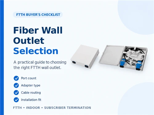
A fiber box that accommodates the required connectors may still lack room for cable entries, service loops or equipment replacement. Likewise, a cabinet large enough for an Ethernet switch may need a separate fiber management module. The selection process below helps engineers and procurement teams turn these requirements into a usable bill of materials.
1. Establish the site conditions and network handoff
The first decision is where the incoming optical link ends and how the outdoor devices receive data and power. Record the network architecture, equipment interfaces, route and maintenance arrangements before specifying a box size or connector.
Identify the equipment that receives the fiber
A passive optical network (PON) service terminates at an optical network terminal (ONT). A point-to-point Ethernet link may terminate at a switch or media converter with an optical transceiver. Identify that active device and its power source: the enclosure protects the connections, while the ONT, switch or converter provides the network interface. Plan electrical power separately from the optical link.
Agree who supplies and services the optical termination, active equipment and power system. Record the operator's handoff point where a service provider is involved. Include a passive splitter only where the approved optical network design and loss budget call for one.
Site differences that affect the configuration
| Site | Confirm before ordering | Configuration consequence |
|---|---|---|
| CCTV pole or roadside camera | Direct optical connection or a local Ethernet switch; camera power arrangement; pole dimensions; access for replacement | Provide protected fiber termination, the correct mounting kit and service access. Add a suitable equipment cabinet when active devices need housing. |
| EV charging station | Site gateway interface; operator handoff; approved communications compartment; cable route between chargers and gateway | Determine whether fiber serves a central gateway or individual equipment. Coordinate the communications layout with the charging equipment supplier. |
| Bus shelter or passenger information display | Continuous or scheduled power; fiber route through the structure; available depth; lock access; maintenance ownership | Check that the display and network equipment can be serviced without pulling on the fiber or removing unrelated components. |
For each location, document direct sun, rain, dust, possible flooding, salt exposure, cleaning methods and expected temperature conditions. Include photographs and measured dimensions of the mounting surface, entry route and working area.
Specify the cable for its complete route, checking duct, direct-burial and indoor-transition requirements wherever they apply. Use the outdoor fiber cable range to identify candidates, then request the datasheet for the proposed construction and installation method.
2. Space for fiber, equipment and power
Treat fiber management, active equipment and power as separate space requirements, even when they share one cabinet. Select the enclosure only after a layout shows that each part can be installed, accessed and replaced without disturbing the others.
Choose the enclosure by function
| Function | Suitable starting point | What the layout must accommodate |
|---|---|---|
| Protect a cable joint | Splice closure configured for the cable and environment | Cable anchoring, splice trays, fiber routing and re-entry provisions |
| Present a removable optical connection | Termination box or connectorized terminal | Adapter or hardened port access, connector boots, cable strain relief and slack |
| House powered network equipment | Equipment enclosure designed for the proposed contents | Device mounting, cable access, heat dissipation, power components and electrical provisions |
Product functions can overlap: some closures incorporate connectors or splitters, and some network interface device (NID) enclosures have equipment accommodation options. Check the actual configuration and drawings.
GLORY's GL-NID01 outdoor fiber optic junction box is a candidate for the outdoor handoff. Before adding it to the bill of materials (BOM), match the internal option to the required termination layout. Any proposed ONT or power equipment also needs a configuration-specific review of fit, heat and electrical requirements.
Review the populated cabinet
For the fiber area, allow space for cable anchoring, protected splices, connector access and the required bend radius. For the equipment area, include the device body, plugged-in connectors and the movement needed to remove a transceiver or replace a device. For power, identify the proposed supply, wiring, isolation, protection and any backup equipment with the responsible electrical designer.
Review thermal performance with the proposed equipment installed, accounting for device limits, internal heat sources and solar exposure. Axis's surveillance cabinet documentation illustrates this system approach by identifying compatible switches, power supplies and installation accessories separately.
Put access boundaries on the drawing. A technician should be able to reach the fiber service point through the intended maintenance procedure, with any required electrical segregation and isolation defined by the equipment documentation and local project requirements.
Three illustrative layouts
The following examples show how to apply the selection rules. They are planning examples, not GLORY project records; equipment models and site conditions determine the final design.
CCTV pole with a local Ethernet camera. Assume the camera receives data and power from a local Power over Ethernet (PoE) switch with an optical uplink. The layout needs an incoming-fiber termination, a patch lead to the switch, the switch and its power arrangement. Position the fiber service point so a switch replacement leaves the incoming cable anchored and the splice tray undisturbed. Verify access to the cabinet and its door at the intended mounting height.
EV charging site with a shared gateway. Assume the fiber service ends at one gateway serving several chargers. Place the optical handoff beside the approved gateway location and show the onward communications routes on the drawing. Where a charger communications compartment is proposed, obtain its supplier's layout and access requirements before selecting the enclosure. Size the optical termination for the gateway link and planned additions; document charger connections separately.
Bus shelter with a passenger information display. Assume the network equipment sits inside a shallow service compartment. Check the usable depth with connector boots and cable bends included, then trace the cable route through the shelter frame. Provide a service loop where the display can be disconnected for replacement. Confirm that power availability and key access support the intended operating and maintenance hours.
3. Enclosure specifications that determine site fit
Specify mounting, cable entries, optical capacity, environmental protection and service access together. A populated layout and model-specific documentation should show how the enclosure fits the actual site and its maintenance procedure.
Cable entries, fibers, splices and connectors: four separate counts
| Selection item | Information to request | Failure this helps prevent |
|---|---|---|
| Mounting | Wall or pole arrangement, bracket dimensions, pole range, fixing method and installation orientation | An enclosure arriving with an unsuitable mounting kit |
| Cable entries | Number of cables, round or flat profile, outside dimensions, seal range and unused-entry plugs | A cable that fits through the opening but cannot be sealed or secured |
| Optical capacity | Incoming fiber count, splice quantity, adapter configuration, connected circuits and planned additions | Confusing connector capacity with splice or cable-entry capacity |
| Usable space | Internal dimensions with all accessories fitted, connector clearance and slack route | A lid that closes only by compressing patch cords |
| Environment | Required ingress performance, temperature limits, UV exposure, impact and corrosion requirements | Selecting on a weatherproof label without checking the actual site |
| Maintenance | Door movement, tool access, tray access, replaceable seals and port identification | A routine repair requiring unnecessary disassembly |
For example, both fibers of a two-fiber circuit may share one cable and one entry. For several incoming cables, check each cable's dimensions against the available entry and anchoring positions, then count the required splices. Use a cable-entry schedule alongside the optical connection schedule.
Turn environmental labels into verifiable requirements
IEC 60529 defines the IP classification for enclosure protection. In a purchase specification, connect the requested rating to the exact enclosure model, seals, cable sizes, unused-port closures and installed configuration. Treat temperature capability, UV resistance, impact resistance and corrosion performance as additional requirements to verify.
If immersion is possible, specify the required depth and duration and request evidence for the proposed configuration. The IEC water-protection chart reproduced in Figure 3 of a European Commission JRC report distinguishes temporary immersion, numeral 7, from continuous immersion under agreed conditions, numeral 8. Use these definitions to frame the requirement, then confirm the product's tested conditions.
Plan how the enclosure will be opened and resealed. The AXIS T98A-VE installation guide, for example, advises against assembly or disassembly during rain to avoid condensation. Follow the selected enclosure manufacturer's instructions for entry seals, closure and any approved condensation-control accessories.
Verify access with the cables installed
Check the door and tray movement with the intended cables, adapters and equipment in place. Include space to operate a connector latch and inspect or clean the end face. Size service loops using the specific cable manufacturer's bending limits; distinguish bend radius from bend diameter. The FOA cable installation guidance explains why pulling tension, bending and twisting must be controlled during installation.
Apply the access check to the maintenance task: for the CCTV layout, simulate replacing the switch or camera lead while the feeder remains secured. At the EV site, trace the gateway's optical connection and confirm which service team can reach it. At the bus shelter, check the display replacement path with the compartment door open and the planned service loop in place.
4. When pre-termination, field splicing or a mixed approach fits
Pre-terminated assemblies are useful when interfaces and route lengths are known and the protected connectors can pass through the route. Field fusion splicing offers flexibility when lengths are uncertain or connector passage is difficult; a mixed approach can retain that flexibility while simplifying repeatable final connections.
| Illustrative site condition | Approach to evaluate | Check before committing |
|---|---|---|
| CCTV poles with repeatable cabinet-to-camera routes and an exposed removable optical connection | Matched hardened terminal and pre-terminated optical lead | Camera or converter interface, lead length, strain relief and replacement access |
| EV charging site with an uncertain feeder length but a fixed gateway position | Field-spliced feeder with a factory-terminated patch lead to the gateway | Feeder service loop, protected splicing location, gateway interface and ownership of each link section |
| Repeated bus shelter designs with measured routes and accessible assembly openings | Factory pre-terminated assemblies | Connector passage through the frame and entry seals, storage for length tolerance and display replacement clearance |
| Retrofit at any of these sites where the protected connector cannot pass through the route | Cable installed before final termination | Cable installation limits, accessible termination location and space for splicing equipment |
Connector passage and length allowance
Check the dimensions of the pulling protection, connector body and fanout against the narrowest opening and bends along the route. Verify both installation passage and final sealing: a cable jacket may fit a gland that is too small for its assembled connector. Where an entry must open around the cable, specify an approved split-entry arrangement with the enclosure supplier.
Specify the installed length, routing allowance, service loops and permitted length tolerance. Identify where surplus cable will be stored. Protect the connectors during installation using the assembly manufacturer's method rather than pulling directly on connector bodies.
Specify both the optical and mechanical interfaces
Record the connector family, fiber type, polish and circuit arrangement at each end. APC means angled physical contact; UPC means ultra physical contact. Do not mate APC and UPC end faces, as noted in the FOA connector troubleshooting guidance. Where two different equipment interfaces are involved, order an assembly that matches each mating interface correctly.
For hardened connections, match the optical interface, housing, locking mechanism and sealing arrangement as one pair. GLORY's Sticklok terminal and cable assembly platform describes cable profiles and interface configurations; use approved drawings and sample checks to confirm the proposed pairing before volume ordering.
The complete installed cost
Compare assemblies, termination labor, testing, spare lengths, installation access and repair arrangements. Pre-termination moves connector preparation to the factory, but the project still needs route planning, careful handling, inspection and field acceptance. Request a project-specific comparison instead of applying a universal percentage saving.
GLORY Product Recommendations for Outdoor Fiber Connectivity
Match the component to its role in the site layout. The products below are listed on GLORY's official website; the application suggestions are selection guidance, not claims of completed CCTV, EV charging or bus shelter projects.

GL-NID01 Outdoor Fiber Optic Junction Box
A candidate for a protected optical handoff. The official listing specifies a PC+ABS enclosure, pole or wall mounting, and SPL, ONU and LGX configuration options.
Listed details: 251.22 × 261.26 × 75 mm; 1 cable entry in / 1 out.
Use when: The optical service point beside a CCTV cabinet, EV site gateway or bus shelter compartment.
Before ordering: Confirm the internal option, cable seals and populated layout. Review powered equipment fit, heat and electrical provisions separately.

Sticklok Fiber Optic Terminal Platform
A hardened connector platform with MTC branching, MTS splitter, MTT cascade and matched STC cable assembly options. Select the network function before the port configuration.
Listed details: MTC branch options: 4F–24F. The terminal listing states IP68 and IK08.
Use when: Repeated outdoor access points where matched removable optical connections simplify installation and replacement.
Before ordering: Confirm the terminal–assembly pairing, cable profile and installed sealing conditions. Use splitter versions only where the optical design requires them.

GYXTW Outdoor Fiber Optic Cable
An outdoor feeder cable listed for duct and aerial installation, with available fiber counts from 1 to 24.
Listed details: Published installation types: duct and aerial.
Use when: Feeder routes to roadside CCTV, charging site gateways and bus shelter access points when the route matches these installation methods.
Before ordering: Specify fiber type, count, outside diameter, pulling and bending limits, support arrangement and indoor transition requirements.

GYTA53 Outdoor Fiber Optic Cable
An outdoor cable whose product description identifies a double-jacket, double-armored construction for duct and direct-burial applications.
Listed details: Published installation types: duct and direct burial.
Use when: Underground feeder routes where the project calls for an armored cable construction.
Before ordering: Request the exact GYTA53 datasheet before ordering: the current page's specification table uses GYFTY53 model codes. Confirm diameter, construction and entry compatibility for the quoted model.
5. Build an RFQ that supports selection, testing and quotation
A useful request for quotation (RFQ) states the site conditions and required configuration so suppliers can quote the same scope. Include the acceptance requirements at this stage: they affect the assemblies, documentation and site work that must be priced.
Outdoor fiber connectivity RFQ checklist
| RFQ field | Information to provide |
|---|---|
| Application and destination | CCTV, EV charging station or bus shelter; installation country; number of sites |
| Network handoff | PON or point-to-point Ethernet; operator requirements; active equipment model and optical interface |
| Environment | Installation position; sun, rain, flooding, dust, salt or cleaning exposure; required operating conditions |
| Mounting and space | Wall, pole or cabinet; dimensions; photographs; bracket requirements; access restrictions |
| Cable specification | Fiber type and count; cable construction; round or flat dimensions; route and installation method |
| Entries and capacity | Incoming and outgoing cable quantities; splice quantity; adapter or hardened-port quantity; planned additions |
| Connections | Exact connector and mating-port types; APC or UPC at each interface; simplex or duplex arrangement; connection schedule |
| Assembly lengths | Measured routes, service-loop locations, length tolerance and connector pulling protection |
| Equipment accommodation | Device dimensions with connectors fitted; power equipment; heat and access information where applicable |
| Supply scope | Empty or populated enclosure; trays, pigtails, adapters, seals, plugs, brackets, assemblies and labels required |
| Evidence and tests | Model-specific environmental evidence; factory optical results; field test method, wavelengths, acceptance limits and report format |
| Commercial requirements | Quantities by configuration, sample approval, destination, delivery schedule, spare parts and warranty expectations |
Attach the drawing that resolves the main site uncertainty. For CCTV, include the pole and cabinet arrangement plus the camera-side interface. For EV charging, include the gateway location, approved communications space and the scope supplied by the charger vendor. For a bus shelter, include a dimensioned service-compartment drawing, frame openings, display removal path and access arrangements. These details let the supplier assess the configuration before preparing a quotation.
Agree how the installed link will be accepted
Separate factory assembly records from field acceptance results. Define the connection schedule, connector inspection, continuity checks and end-to-end insertion-loss measurement against the project loss budget. Where optical time-domain reflectometer (OTDR) traces are required, specify their purpose and settings alongside the optical loss test set (OLTS) or source-and-power-meter measurements. The FOA fiber testing reference explains the different roles of these measurements.
Also record cable identification, populated enclosure photographs, the approved sealing arrangement and any deviations from the drawing. Keep factory records as the assembly baseline and field results as evidence of the completed installation. Agree a separate service check with the system integrator: camera connectivity for CCTV, gateway communication for the charging site, or display data delivery for the bus shelter.
Send GLORY a configuration to review
GLORY Optical's OEM and project configuration capabilities cover fiber enclosures, cable assemblies, interfaces and associated accessories. Submit the checklist with site photographs, a connection sketch and the required quantities so the proposed passive components can be reviewed together.
Contact GLORY Optical for selection support and a project quotation. Ask for a configuration-specific proposal identifying the enclosure, cable entries, optical connections, mounting accessories, test documentation and any items to be supplied by others.