

Product Overview
Inside the GL-07 MPO Fiber Distribution Box
The box cassette, translucent cover and removable adapter plate organize the MPO side and the adapter side in one ABS enclosure. The cover allows fiber observation; the adapter plate can be disassembled for LC duplex or SC simplex adapters without flange.
Adapter Plate Layout
The LC layout uses 12 LC duplex adapters without flange. The adapter plate drawing numbers the positions 1–12 in the upper row and 13–24 in the lower row, so the port map follows the drawing.
Colour and capacity: The standard adapter plate colour is black. Blue, green, aqua and magenta plates in the photographs show the four build variants; they do not change the stated capacity.
Technical Selling Points
GL-07 Construction and Connection Features
Defined MPO-to-LC Capacity
The box takes 2 MTP/MPO adapters and 12 LC duplex adapters without flange. Each duplex adapter carries two ports, and the enclosure maximum is 24 fibers for connection and distribution.
Removable Adapter Plate
The adapter plate can be disassembled and accepts LC duplex or SC simplex adapters without flange. A project can specify the appropriate adapter format before loading the box, rather than treating the photographed LC layout as the only connection path.
Splice Route with Named Modules
For the splice application, the enclosure can load 1 pc PG9 cable gland and 2 pcs splice modules OS-16. A fiber optic heat shrinkable sleeve and LC or SC pigtails complete the cable-entry, splice and adapter path within the box.
Translucent Cover and ABS Housing
The ABS box cassette carries a translucent cover so fibers can be observed with the cover fitted. The ABS plastic is specified as light weight and high impact. The cover provides a view of the fiber arrangement within the enclosure.
Press Buckle Mounting
The press buckle design is specified for a fiber optic patch panel and rack. It identifies the attachment mechanism and intended mounting location for the GL-07 when planning the panel position and box orientation.
Four Selectable Build Variants
The build variants are OS2(UPC), OS2(APC), OM3 and OM4. Each can be configured with its own LC duplex adapter, patch cord, adapter plate, cable gland and splice module. State the chosen variant on the order so a photographed plate colour is not mistaken for the black standard.
Product Family and Configuration
Four GL-07 Build Variants
The four build variants are labelled OS2(UPC), OS2(APC), OM3 and OM4. The coloured plates are variant presentations in the photographs; the standard adapter plate colour is black.


Published Product Data
General Technical Specifications
General data for the GL-07 MPO fiber distribution box, with adapter quantity, LC port count and fiber capacity recorded as separate fields.
| Parameter | GL-07 specification | Clarification |
|---|---|---|
| Product model | GL-07 | MPO / MTP fiber distribution box |
| Enclosure | ABS plastic box cassette, cover and adapter plate | Translucent cover for fiber observation |
| MTP/MPO adapter capacity | 2 pcs | Separate from LC adapter count |
| LC adapter capacity | 12 LC duplex adapters without flange | Or 12 SC simplex adapters without flange |
| LC port count | 24 LC ports | Two ports per LC duplex adapter |
| Fiber capacity | Maximum 24 fibers | Connection and distribution |
| Splice provision | 2 pcs splice modules OS-16 | Module quantity only |
| Cable entry component | 1 pc PG9 cable gland | Listed for the splice route |
| Mounting | Press buckle design | Fiber optic patch panel and rack |
| Standard adapter plate colour | Black | Photographs show coloured variant plates |
| Body width | 92 mm | Dimension drawing |
| Overall height / body height | 137 mm / 125 mm | Dimension drawing |
| Depth | 26 mm | Dimension drawing |
| Overall width with side mounting clips | 102 mm | Dimension drawing |
| Adapter plate face height | 29.5 mm | Dimension drawing |
Model and Capacity Table
| Model | Build variants | MTP/MPO adapters | LC duplex adapters | LC ports | Fiber capacity | Splice provision |
|---|---|---|---|---|---|---|
| GL-07 | OS2(UPC), OS2(APC), OM3, OM4 | 2 pcs | 12 pcs without flange, or 12 SC simplex | 24 | Maximum 24 fibers | 2 pcs splice modules OS-16 |
All four build variants share this capacity. They differ in the variant label and in the adapter plate colour shown in the photographs, which is a variant presentation rather than the black standard.
Cable Entry and Interfaces
Cable and Connector Compatibility
The GL-07 supports two connection routes: MPO patch-cord distribution or entry through a PG9 cable gland for splicing to pigtails.
| Position or route | Component | Configuration choice |
|---|---|---|
| MPO side | 2 MTP/MPO adapters | MPO-LC or MPO-SC patch cord |
| Adapter plate | 12 LC duplex adapters without flange | Or 12 SC simplex adapters without flange |
| Cable entry | 1 pc PG9 cable gland | Splice application |
| Splice and termination | 2 pcs splice modules OS-16; fiber optic heat shrinkable sleeve | LC pigtail or SC pigtail |


Application Scenarios and Solutions
MPO Fiber Distribution Box Applications in Patch Panels and Racks
Select the route by the connection components required at the rack or patch-panel position.
MPO Fiber Distribution Box for MPO-to-LC Patching
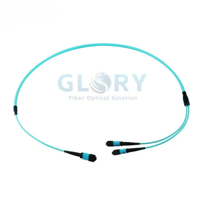
Choosing a box by its fiber figure alone leaves the patch-cord and adapter map undefined. The GL-07 provides 2 MTP/MPO adapter positions on the MPO side and a removable plate for 12 LC duplex adapters without flange on the LC side, so an MTP to LC breakout cable can feed the adapter side. Mount the box at a MPO fiber patch panel or rack. For the project order, identify the OS2(UPC), OS2(APC), OM3 or OM4 variant, the MPO-LC cord and the intended port numbering before the plate is loaded.
MPO-to-SC Patch-Cord Distribution
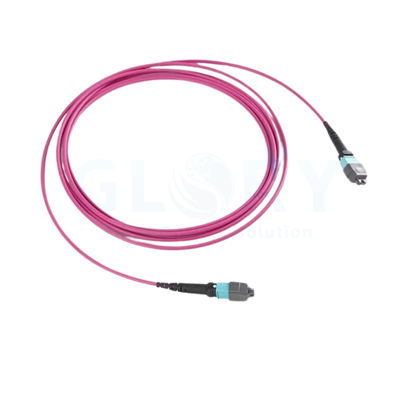
An LC plate should not be assumed when the patching plan calls for SC connections. The disassemblable GL-07 adapter plate also accepts SC simplex adapters without flange, and an MPO-SC patch cord is the alternate Application 1 route. At a rack or fiber optic patch panel, this places the selected patch cord between the MTP/MPO adapter side and the SC adapter side. Confirm the SC simplex adapter choice, the MPO-SC patch cord, the selected build variant and the port map in the project configuration before ordering.
Spliced Fiber Entry at a Rack Distribution Point
A patch-cord route does not describe a build that brings a cable into the box for splicing. Application 2 uses 1 pc PG9 cable gland at the entry, 2 pcs splice modules OS-16, a fiber optic heat shrinkable sleeve, and LC or SC pigtails leading to adapters without flange. In a rack or fiber optic patch panel, these components provide the splice-and-pigtail route within the GL-07 cassette. Before procurement, specify the pigtail and adapter choice, and the build variant.


Installation and Selection Guidance
Specify the GL-07 Layout Before Ordering
Check the adapter and patch-cord route against the panel drawing, then check the dimension drawing for fit. Where the port format is still open, read MPO to LC breakout vs duplex LC before fixing the adapter choice.
Project Selection Checklist
-
✓Select OS2(UPC), OS2(APC), OM3 or OM4 exactly as a build variant.
-
✓Choose 12 LC duplex adapters without flange, or 12 SC simplex adapters; the box maximum remains 24 fibers.
-
✓For patching, identify the MPO-LC or MPO-SC patch cord and MTP/MPO adapter positions.
-
✓For splicing, identify 1 pc PG9 cable gland, 2 pcs splice modules OS-16, heat shrinkable sleeves and LC or SC pigtails.
-
✓Check the press buckle position in the fiber optic patch panel or rack against the dimension drawing.
Drawing measurements: 92 mm body width, 137 mm overall height, 125 mm body height and 26 mm depth. The overall width including side mounting clips is 102 mm; the adapter plate face height is 29.5 mm. Use the labelled dimensions rather than combining them into an unqualified size string.

Ordering Configuration
| Order field | Product data | Specify for the project |
|---|---|---|
| Build variant | OS2(UPC), OS2(APC), OM3, OM4 | Choose one listed label. |
| Adapter plate | Standard colour black; photographed variant plates blue, green, aqua and magenta | Identify the required build variant and plate presentation. |
| Adapter arrangement | 2 MTP/MPO adapters; 12 LC duplex adapters without flange, or 12 SC simplex adapters without flange | Mark the adapter choice and port numbering. |
| Patch-cord route | MPO-LC or MPO-SC patch cord | Choose the patch cord for Application 1. |
| Splice route | 1 pc PG9 cable gland; 2 pcs splice modules OS-16; heat shrinkable sleeve; LC or SC pigtail | Choose the listed components for Application 2. |
| Packaging | Inner box: 16.5 × 11.5 × 3.7 cm, 0.2 kg, 1 pc. Master carton: 36 × 34.5 × 39.5 cm, 13.5 kg, 60 pcs. | Plan carton quantities with these units. |
OEM and Project Configuration
Document the GL-07 Build Variant and Component Route
For an OEM GL-07 MPO fiber distribution box order, identify the variant label, adapter format and either the patch-cord or splice route. Each of the four variants can be configured with an LC duplex adapter, a patch cord, an adapter plate, a cable gland and a splice module.
Variant and Plate
Record OS2(UPC), OS2(APC), OM3 or OM4 and distinguish the photographed coloured plate from the black standard adapter plate.
Port and Adapter Map
Record the adapter arrangement and the port numbering, and specify SC simplex adapters instead of LC duplex if that alternative is selected.
Connection Components
For Application 1, choose an MPO-LC or MPO-SC patch cord. For Application 2, identify the PG9 gland, the OS-16 splice modules, the heat shrinkable sleeve and the pigtails.
Company Background
Glory Optical and GL-07 Project Supply
Glory Optical Communication states on its company page that it was founded in 2008 and operates a 20,000 m² manufacturing facility in Ningbo, Zhejiang. Its portfolio covers more than 300 passive optical products, with supply to customers in more than 50 countries and OEM/ODM project support.
Enclosure Operations
The Ningbo operation lists molding, CNC, enclosure assembly, material preparation, warehouse and packing functions. Those functions are relevant to the GL-07 ABS cassette, cover, adapter plate and carton configuration.
Associated Optical Parts
Assembly support covers fiber boxes, splice trays, adapters, pigtails, PLC splitters and cable-management parts. For GL-07, the relevant project list is the box, adapters, patch cord or pigtails, gland and OS-16 splice modules.
Hot Tags: mpo fiber distribution box, China mpo fiber distribution box manufacturers, suppliers, factory, data center cabling, data center fiber cabling, mtp mpo, Mtp Mpo Fiber, Mtp Mpo Fiber Breakout Cable, Mtp To Lc Breakout Cable