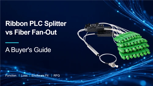
A ribbon PLC splitter divides optical power from an input fiber among multiple output fibers. A fiber fan-out separates existing fibers into protected, individually routed paths. "Ribbon" describes how fibers are organized, rather than proving that light is being split. An assembly can contain both functions, so confirm its optical diagram, fiber arrangement and termination details before ordering.
That distinction follows the separate roles described in Corning's cable furcation guide and the FOA explanation of optical splitters. For an ODN designer or purchasing team, the immediate task is to identify the required function and describe it clearly enough for a supplier to quote.
What Does "Ribbon Splitter" Mean on a Purchase Order?
"Ribbon splitter" can identify an optical power splitter, a fiber-management assembly or a preparation tool. The purchase order needs the intended function, a fiber-path drawing and a part specification because the name alone does not distinguish those products.
A PLC, or planar lightwave circuit, splitter contains an optical circuit that distributes power between branches. Ribbon fibers or individual leads connect that circuit to the rest of the network. A fan-out provides an organized transition between grouped fibers and separate legs. A ribbon-splitting tool acts on the ribbon material during preparation.
| Item being specified | What it does | Evidence to request |
|---|---|---|
| Ribbon PLC splitter | Distributes optical power through a PLC circuit and presents the selected input/output arrangement | Optical topology, split ratio, output format and port-level optical limits |
| Pure ribbon fan-out or ribbon pigtail assembly | Protects and organizes existing fiber paths for routing or termination | Fiber count, continuity map, leg construction and termination drawing |
| Ribbon-splitting tool | Mechanically separates compatible ribbon fibers or ribbon subgroups during preparation | Tool model, supported ribbon construction and manufacturer's procedure |
A tool listing illustrates why the wording matters. Lightera's FITEL S233 documentation describes ribbon preparation and explicitly excludes use on live fiber or for a mid-span strip. Those restrictions belong to that tool. A supplier's use of the word "splitter" does not make another tool suitable for the same procedure.
For a broader comparison of optical technologies and housings, use the fiber optic splitter classification guide. Here, the buying decision starts with the fiber path inside the specific assembly.
Follow the Fiber Path Through the Assembly
A balanced 1×8 PLC splitter distributes the power from one input across eight outputs. An eight-fiber fan-out keeps eight separate fiber paths available for individual termination; it does not create eight copies of the signal carried by one fiber.
The two arrangements can look similar after their leads have been connectorized. The functional drawing should show which one is being offered.

| Functional example | Path through the assembly | Meaning for the project |
|---|---|---|
| Balanced 1×8 PLC | One input fiber → PLC circuit → eight output fibers | The link budget must include the optical split |
| Pure eight-fiber fan-out | Eight existing fibers → protected fan-out legs → eight corresponding terminations | Each required path must have a defined fiber-to-termination assignment |
These are functional examples, not drawings of a particular Glory model. A PLC splitter can also have a fan-out section, so "PLC splitter" and "fan-out" are not mutually exclusive descriptions of a complete assembly.
For a concrete mechanical example, Corning's RIB-FAN-12-36 kit is specified for 12 ribbon fibers and 0.9 mm protective tubing. That tubing organizes existing fibers. It is not a 1×12 optical splitter.
Also keep the connector format separate from the function. An MPO connector can carry several fiber paths in one ferrule; its presence does not establish a PLC split ratio or show which fibers are connected internally. Request the optical diagram and port map even when the connector name appears familiar.
Choose the Output Format of a Ribbon PLC Splitter
Specify optical topology, fiber organization and termination as separate fields. The output arrangement must match the receiving splice tray, adapter panel or other approved termination hardware, even when two quotations use the same nominal split ratio.
Begin at the receiving end. A panel that expects connectorized individual leads needs a different termination arrangement from a tray designed for a ribbon splice. The manufacturer must confirm that the chosen fibers, protection and preparation process work together.
| Output choice | What procurement should confirm | Effect on integration |
|---|---|---|
| Bare individual fibers | Coating dimensions, fiber identity, preparation length and protection up to the splice | Requires a defined handling and splice-routing plan |
| Ribbon fibers | Fiber count, ribbon construction, sequence and compatibility with the intended splice process | Must match ribbon handling, holders, protectors and tray arrangements |
| Individually protected fan-out legs | Tubing dimensions, leg lengths, exit direction and retention | Adds mechanical protection but also needs routing and storage space |
| Connectorized leads | Connector family, polish, termination count, labels and mating interface | Requires the corresponding adapters and access for inspection and cleaning |
A 0.9 mm leg dimension describes its protection format. It does not specify the glass diameter, optical mode, split ratio or connector polish. Likewise, the word "ribbon" does not establish whether both ends are ribbonized or whether the ordered assembly finishes as individual legs.
Glory's ribbon fan-out PLC family combines power division with individual output routing. Its product page lists several package formats; the ordered input/output configuration still needs a drawing.
 |
Glory Ribbon Fan-Out Fiber PLC SplitterA PLC splitter assembly with individually routed output leads. Specify the input/output arrangement, package and termination options for the intended enclosure. Original Glory product photo. The ordered split ratio and interfaces follow the approved drawing. View ribbon fan-out PLC splitter |
For termination work without optical power division, a ribbon pigtail assembly is a separate product choice. Confirm the bonded or grouped fiber section and the connector configuration in the approved specification. A photograph of colored branches cannot establish the internal arrangement.
Check Splitter Loss With a Defined Test Boundary
Specify the guaranteed maximum loss for the required paths, wavelengths and finished configuration. The number used in the link budget must have a stated measurement boundary so the project can account for the splitter, connectors and other interfaces consistently.
For an ideal equal-power 1×N split, each output receives 1/N of the input power. The positive attenuation magnitude is 10 log10(N) dB. Real assemblies add excess loss and may include connector interfaces within the reported measurement.
| Balanced split | Calculated ideal loss per output | Conditions and source |
|---|---|---|
| 1×8 | 9.03 dB | Equal-power division only; calculated from 10 log10(8) |
| 1×16 | 12.04 dB | Equal-power division only; calculated from 10 log10(16) |
| 1×32 | 15.05 dB | Equal-power division only; calculated from 10 log10(32) |
| 1×64 | 18.06 dB | Equal-power division only; calculated from 10 log10(64) |
The calculations express the ideal splitting relationship explained by the FOA source above. They exclude excess loss, fiber attenuation and connectors. They are not Glory test results, product acceptance limits or the loss of an unequal-ratio tap.
A quote described as "splitter loss" could refer to an unterminated component or a finished connectorized assembly. Ask the supplier to mark the reference planes and identify the interfaces included in the result. Add only the remaining interfaces when building the channel budget. Otherwise, the same connector loss may be counted twice or missed entirely.

IEC 61300-3-4:2023 covers attenuation measurement methods for optical components. Naming the standard in an RFQ does not prove that a supplied assembly was tested with a particular method. Request the actual procedure, configuration and test record.
For a balanced splitter, compare the highest-loss required path with the agreed maximum and review port-to-port uniformity under the same conditions. Keep wavelength and direction visible in the record. The PLC splitter test-report guide provides the wider document review; this purchase specification should identify exactly which finished configuration those records cover.
Confirm Enclosure Fit With a Routing Drawing
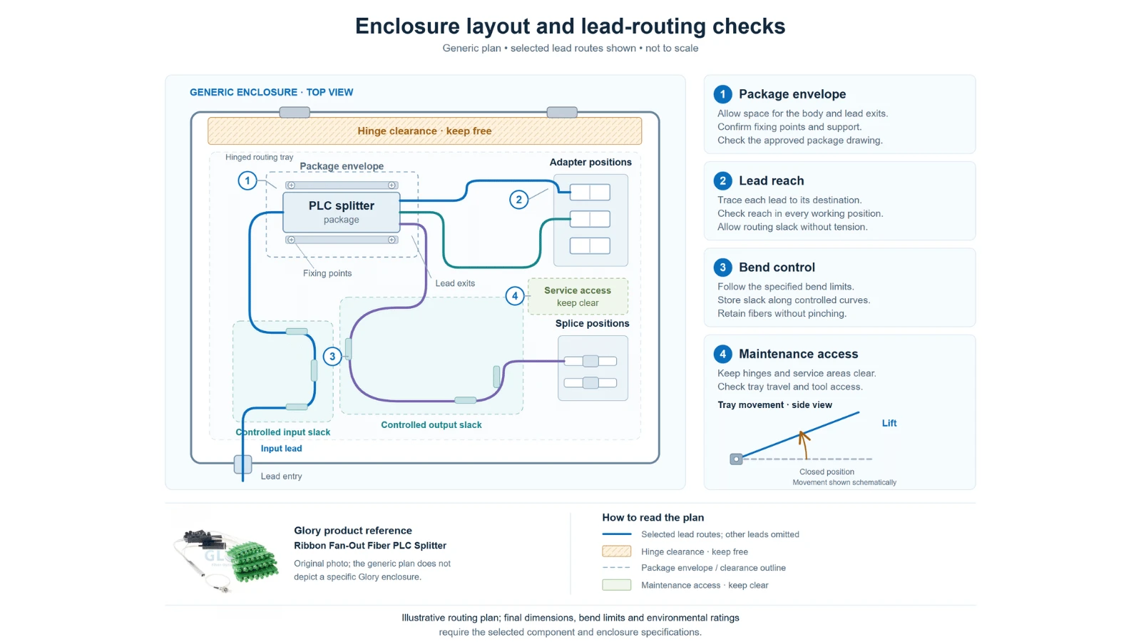
Approval should cover the module body, lead exits, fiber storage and the enclosure's moving parts. Checking the package dimensions alone leaves the branch routing and connector access unresolved.
Place the intended component on the host-enclosure drawing. Mark the splice positions or adapters it must reach, the retention points and the space needed to open the tray. Use the minimum bend limits supplied for the actual fibers, protective tubes and finished assembly; a fiber-category designation cannot define every handling limit.
Four mechanical checks are useful before approving the sample:
- Confirm the fixing method and support for the module or furcation body.
- Trace every required lead to its destination with the tray in its working positions.
- Reserve access for splicing, connector inspection or cleaning, as applicable.
- Check that stored leads remain clear of hinges, covers, cable clamps and other moving parts.
The required capacity also has several units. Output fibers, single-fiber splices, adapter positions and subscriber drops are separate counts. A panel described as "16 ports" does not by itself define the optical splitter, the available splice space or how many connectorized leads can be stored. Use the fiber-box capacity guide to review those distinctions.
For outdoor use, specify the host enclosure and the installed configuration. A component inside a protective module does not automatically have the enclosure's ingress rating. The sealing, cable entries, retention and permitted environmental conditions need their own supporting specifications.
Put the Configuration in a Quote-Ready RFQ
A usable RFQ ties the optical function to an output drawing and acceptance requirements. Give the supplier enough detail to identify one configuration, then keep the agreed fields under a drawing or specification revision.
The fields below can be copied into an enquiry. Leave an item explicitly open for engineering review when it has not been decided.
| RFQ field | Information to supply |
|---|---|
| Required function | PLC optical power division, pure fiber fan-out, or a combined assembly |
| Optical topology | Input/output count, balanced or unequal splitting, and the required optical path diagram |
| Fiber specification | Mode, fiber standard, count, construction and identification sequence |
| Input and output format | Ribbon or individual fibers; coating or protective-tube dimensions; any required transitions |
| Termination | Bare or connectorized ends; connector family and polish; adapter or splice interface |
| Mechanical layout | Package envelope, retention, exit direction, lead lengths, reference points and tolerances |
| Host equipment | Enclosure model, usable layout, splice tray or adapter positions and environmental requirements |
| Optical acceptance | Applicable paths, wavelengths, direction, maximum insertion loss, return loss and uniformity requirements |
| Measurement boundary | Reference method, included interfaces and required report fields |
| Identification and delivery | Quantity, drawing revision, branch labels, traceability, packaging and requested date |
An illustrative request might specify a balanced 1×8 PLC with individual protected outputs intended for splicing inside a named distribution box. It should also define the input arrangement, output sequence and lead-length reference points. The supplier then confirms a suitable package and optical limits against that configuration.
This example is an RFQ format, not a standard Glory configuration. Connector options, tolerances and the inspection plan require agreement before the order is released.
For a pure fan-out, replace the split-ratio requirement with a continuity and fiber-assignment map. Do not apply PLC split-loss allowances to a component that only protects existing fibers. Define the optical limits for any connectors or splices that are actually included.
Verify the First Article Before Releasing the Batch
The first article should match the approved configuration and have records that identify what was measured. Review it against the drawing before using its appearance or a single PASS result as the basis for batch acceptance.
A practical review can follow four steps. This is a procurement workflow; the project specification determines the test methods and acceptance limits.
- Match identity and configuration. Compare the sample label with the part number and drawing revision. Confirm the function, input/output arrangement, fiber sequence, lead lengths, connector details and required accessories. Resolve differences before treating the sample as the approved build.
- Check physical routing and end faces. Trial-fit the assembly in the intended enclosure and operate the tray or cover through its normal movement. For connectorized ends, inspect and clean with suitable equipment and procedures. IEC 61300-3-35:2022 addresses visual inspection and makes clear that it supplements optical performance measurement.
- Review the optical evidence. For a PLC, obtain results for the agreed input/output paths at the specified wavelengths and directions, with the reference boundary stated. For a pure fan-out, verify the required assignments and the optical performance of the included terminations. Check measured results against the limits approved for that sample.
- Record the release decision. Retain the approved drawing, sample identity, fit observations, test configuration and results. Record any accepted deviation and its scope. Release the batch only against the agreed version, or hold it while unresolved configuration or performance differences are corrected.
A clean connector image cannot establish insertion loss or return loss. Conversely, an optical result does not confirm that a lead reaches the intended adapter or carries the correct label. Keep the physical, mapping and optical records connected to the same sample.
When shipments arrive, check the agreed identification and documentation against the released configuration. If a supplier changes the package, fiber construction or termination details, review the change before assuming that the earlier sample approval still applies.
Send a Configuration That Can Be Reviewed
Start the enquiry with the required optical function and the host-enclosure layout. Add the input/output arrangement, lead details and acceptance limits so the supplier can review the component as it will be installed.
For a Glory ribbon PLC assembly, send the split ratio and output routing requirements. For a pigtail or pure fan-out, send the fiber assignment and termination plan. Include the drawing revision, quantity and requested delivery date.
Send the enclosure drawing and required fiber paths for configuration review and quotation.
Confirm the function and output layout.
Send the enclosure drawing with your RFQ.
Request a configuration review