Product Overview
High-Density Ribbon Fiber Splitter for Managed PLC Output Routing
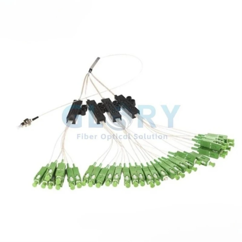
A PLC chip divides optical power, while the fan-out assembly organizes the resulting channels into separate 0.9 mm fibers that can be routed, terminated or spliced inside a host enclosure. This product is not itself an outdoor terminal box: environmental protection, cable anchoring and mounting depend on the patch panel, distribution box, splice closure or cabinet that contains it.
What the Product Does
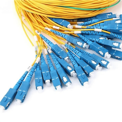
It combines planar lightwave circuit splitting with a ribbon-to-single-fiber fan-out arrangement. The output format reduces the need to manage a loose bundle of unrelated pigtails when many channels must leave one compact splitter package.
Where It Is Integrated
Typical host locations include ODFs, fiber distribution boxes, rack or wall patch panels, splice closures and other protected FTTH, PON, CATV or telecom distribution nodes with sufficient routing space and bend control.

Internal Optical Path
Inner Structure of the Fan-Out Ribbon PLC Fiber Splitter
The diagram identifies the functional path from the input fiber array through the planar lightwave circuit chip to the output fiber array. The fan-out assembly then routes the splitter outputs into separate ribbon or 0.9 mm fiber channels according to the ordered configuration.

Original structure diagram from the product page. It illustrates the optical path and component relationship rather than package dimensions.
The drawing is a functional schematic. Package size, input/output fiber format, connector type and fiber length must still be confirmed for the selected 1×N or 2×N model.
Technical Selling Points
Six Procurement-Relevant Features of the Ribbon Fiber Splitter
1×N and 2×N Project Coverage
The source page lists 1×2, 1×4, 1×8, 1×16, 1×32 and 1×64 models, plus 2×2 through 2×64 configurations. Buyers can standardize one fan-out product family across feeder-sharing and dual-input designs, while confirming optical limits separately for any 2×N model because the original page publishes a performance table only for 1×N units.
0.9 mm Fan-Out Output Structure
Ribbonized channels transition into individual 0.9 mm fiber outputs. Compared with leaving all channels in a flat ribbon, the separated branches can be routed to individual adapters, splice positions or equipment ports inside a host enclosure, helping technicians identify and manage each optical path during assembly and later service.
Ratio-Specific Optical Limits
At 23°C, the published maximum insertion loss rises from 3.8 dB for 1×2 to 20.3 dB for 1×64. Channel uniformity is specified from 0.5 to 1.7 dB and PDL from 0.2 to 0.4 dB, allowing the project optical budget to be checked against the selected ratio rather than a generic splitter claim.
1260–1650 nm Operating Band
The stated wavelength range covers 1260–1650 nm, with G.657.A1 listed as the standard fiber option and other fiber configurations available by request. This supports common access-network wavelengths while giving procurement teams a defined fiber item to place in the BOM instead of describing the assembly only as "single-mode."
Three Published Package Formats
Basic, 900 μm SFF and ABS module dimensions are listed by split ratio. A 1×8 basic package is 4 × 4 × 40 mm, while a 1×64 ABS module is 18 × 115 × 140 mm. Selecting the package before enclosure design reduces the risk of inadequate tray area, exit clearance or fiber-storage space.
Defined Reflection and Temperature Values
Return loss and directivity are each specified at a minimum of 55 dB, with operating and storage ranges of −40°C to +85°C. These are component values; outdoor deployment still requires a host enclosure with the project-required sealing, cable retention and installation rating.
Product Family
Ribbon Fan-Out PLC Splitter Configuration Options
Split ratio describes optical division, not enclosure port capacity. Connectorized lead count, adapter count and available mounting positions must be confirmed as separate BOM items.
| Configuration family | Listed ratios | Input fibers | Output fibers | Published optical table | Procurement note |
|---|---|---|---|---|---|
| 1×N | 1×2, 1×4, 1×8, 1×16, 1×32, 1×64 | 1 | 2, 4, 8, 16, 32 or 64 | Yes, on the original product page | Select ratio from the optical budget and host-enclosure capacity. |
| 2×N | 2×2, 2×4, 2×8, 2×16, 2×32, 2×64 | 2 | 2, 4, 8, 16, 32 or 64 | No ratio-specific values published on the original page | Request the approved datasheet and test limits before ordering. |
Standard Versus Optional Configuration
The original page identifies 0.9 mm fan-out fibers and G.657.A1 as the stated base format. Integrated adapters, connector type, polish, pigtail length, labels and packaging are order-specific options and should not be treated as defaults from the product photographs.
Technical Data
General Technical Specifications for the Ribbon Fiber Splitter
The following values are taken from the specified original product page. Items not published there-such as housing material, IP/IK rating, weight, tensile strength and installation temperature-are intentionally omitted.
| Product model | Ribbon Fan Out Fiber PLC Splitter | Product family | Fan-out PLC splitter / ribbon fiber splitter |
|---|---|---|---|
| Split configurations | 1×2 to 1×64; listed 2×2 to 2×64 options | Output format | Individual 0.9 mm fan-out fibers |
| Operating wavelength | 1260–1650 nm | Fiber type | G.657.A1 or customized |
| Return loss | ≥55 dB | Directivity | ≥55 dB |
| Operating temperature | −40°C to +85°C | Storage temperature | −40°C to +85°C |
| Package formats | Basic type, 900 μm SFF type, ABS module type | Installation method | Integration inside a suitable panel, box, closure or cabinet; standalone mounting details not published |
1×N Optical Performance at 23°C
Maximum or minimum values are shown exactly according to the original product-page table.
| Parameter | Limit | Unit | 1×2 | 1×4 | 1×8 | 1×16 | 1×32 | 1×64 |
|---|---|---|---|---|---|---|---|---|
| Insertion loss at 23°C | Max. | dB | 3.8 | 7.1 | 10.4 | 13.7 | 17.0 | 20.3 |
| Channel uniformity | Max. | dB | 0.5 | 0.6 | 1.0 | 1.3 | 1.5 | 1.7 |
| Polarization-dependent loss (PDL) | Max. | dB | 0.2 | 0.2 | 0.3 | 0.3 | 0.4 | 0.4 |
Model and Package Dimensions
| Split ratio | Input / output count | Basic type | 900 μm SFF type | ABS module type |
|---|---|---|---|---|
| 1×2 | 1 input / 2 outputs | 4 × 4 × 40 mm | 4 × 7 × 60 mm | 10 × 80 × 100 mm |
| 1×4 | 1 input / 4 outputs | 4 × 4 × 40 mm | 4 × 7 × 60 mm | 10 × 80 × 100 mm |
| 1×8 | 1 input / 8 outputs | 4 × 4 × 40 mm | 4 × 7 × 60 mm | 10 × 80 × 100 mm |
| 1×16 | 1 input / 16 outputs | 4 × 4 × 50 mm | 4 × 12 × 60 mm | 18 × 80 × 120 mm |
| 1×32 | 1 input / 32 outputs | 4 × 7 × 50 mm | 6 × 20 × 80 mm | 18 × 80 × 120 mm |
| 1×64 | 1 input / 64 outputs | 4 × 12 × 60 mm | 6 × 40 × 100 mm | 18 × 115 × 140 mm |
Cable and Connector Compatibility
| Item | Published or supported option | What must be confirmed |
|---|---|---|
| Output fiber profile | 0.9 mm individual fan-out fibers | Output color sequence, branch identification and routing length |
| Fiber standard | G.657.A1 stated; customized fiber available | Required fiber standard and compatibility with the project splice/connector plan |
| Connector termination | Integrated adapters/connectors may be specified; Glory's splitter OEM page lists SC/UPC, SC/APC, LC/UPC, LC/APC, FC/UPC and FC/APC | Interface, polish, input/output termination, connector quantity and test acceptance values |
| Lead length | Glory's splitter OEM page lists 0.5 m, 1 m, 1.5 m, 2 m or custom length | Finished length, tolerance, routing allowance and packaging method |
| Host enclosure | Patch panel, fiber distribution box, ODF, splice closure or cabinet | Internal dimensions, bend control, adapter capacity, sealing and cable anchoring |
Application Scenarios
Ribbon Fiber Splitter Solutions for FTTH, PON and High-Density Optical Distribution
FTTH and GPON Distribution Frames
Building a high-ratio PON node from unrelated loose pigtails can create a dense bundle that is difficult to identify and route. The ribbon fan-out PLC splitter combines optical division with individual 0.9 mm branches, so each channel can reach a defined adapter or splice position inside an ODF, fiber distribution hub or termination box. It can connect to feeder-side and subscriber-side equipment using the approved connector plan. Before procurement, confirm the 1×N or 2×N ratio, worst-port loss allowance, package dimensions, fiber length, connector polish and available adapter positions.
Outdoor FTTH Handholes and Splice Closures
A bare or connectorized splitter should not be treated as an independently sealed outdoor product. For an outdoor network or handhole, the ribbon fiber splitter must be installed inside a closure or distribution enclosure with the required project sealing, cable retention and routing space. Its compact basic or 900 μm SFF package can support dense internal layouts, while separate fan-out branches route toward splice trays or adapters. Buyers should verify the host enclosure's IP rating, branch exit method, bend control, splitter mounting arrangement and the exact environmental test requirements before approving the BOM.
CATV, IPTV and Shared Optical Distribution
Using only the nominal split ratio can hide the actual loss assigned to the farthest or lowest-power branch. The published table gives ratio-specific insertion loss, channel uniformity and PDL values across 1×2 to 1×64, which allows a CATV, IPTV or passive broadcast design to reserve the splitter loss before adding connectors, splices and fiber attenuation. The component is typically placed in a rack panel, cabinet or protected distribution box between the optical source and downstream branches. Procurement should confirm operating wavelength, return-loss requirement, connector polish, test method and accepted worst-port result.
OEM Patch Panels and Custom Distribution Assemblies
Specifying "one ribbon splitter" without the package and lead arrangement can produce a component that does not fit the intended panel. The published dimensions change with both split ratio and package type, from a 4 × 4 × 40 mm basic unit for lower ratios to an 18 × 115 × 140 mm ABS module for 1×64. Glory can use the project BOM and drawings to align splitter ratio, package, connector termination, lead length, labels and packaging with a custom enclosure. Approval should cover drawings, routing clearances, connector orientation and sample test data before batch production.
Selection and Installation Guidance
How to Specify a Ribbon Fan-Out PLC Splitter
- 1
Approve the optical split first.Select 1×N or 2×N from the network topology and calculate the complete path using the ratio-specific worst-case splitter loss, connector pairs, splices, fiber attenuation and engineering margin.
- 2
Match the package to the host enclosure.Compare the published basic, 900 μm SFF or ABS module dimensions with available tray area, exit clearance and storage space. Do not use a 1×8 drawing to approve a 1×32 or 1×64 assembly.
- 3
Define the complete termination plan.State fiber standard, input/output connector type, UPC or APC polish, lead length, adapter arrangement, branch labels and whether the assembly is supplied unterminated or factory connectorized.
- 4
Separate component ratings from enclosure ratings.The splitter page publishes temperature values but no IP or IK rating. For outdoor or handhole installation, specify the protection, sealing and cable-retention requirements for the host closure or box.
- 5
Request model-specific acceptance data.For 2×N units, customized fibers or connectorized assemblies, obtain the approved datasheet, drawing and test limits. Reference-sample approval should use the exact production BOM rather than a visually similar splitter.
Project Purchasing Check
Confirm whether insertion loss is stated for an unterminated splitter or a connectorized assembly, and whether the value represents a typical result or the contractual maximum. Connector loss must not be confused with splitter loss, and the split ratio must not be used as a substitute for the measured worst-port result.
OEM and Project Configuration
Ordering Configuration for Custom Ribbon Fiber Splitter Assemblies
| Ordering field | Options or required information | Approval point |
|---|---|---|
| Splitter topology | 1×2, 1×4, 1×8, 1×16, 1×32, 1×64; listed 2×N models | Topology and optical budget |
| Package | Basic, 900 μm SFF or ABS module | Dimension drawing and host-enclosure fit |
| Fiber | G.657.A1 or project-specified customized fiber | Fiber standard, color sequence and length tolerance |
| Connector / polish | Project-specific; splitter OEM options include SC, LC or FC with UPC/APC variants | Input/output interface map and connector count |
| Lead length | 0.5 m, 1 m, 1.5 m, 2 m or custom options listed by Glory | Finished-length tolerance and packaging radius |
| Identification | Branch labels, product label, customer logo and packaging | Artwork, label position and revision control |
| Quality documents | Model datasheet, drawing, optical test records or project-defined inspection documents | Acceptance limits and sampling plan |
Drawing and BOM Confirmation
Provide the target enclosure drawing, adapter map, splitter ratio, lead exit direction and cable-routing constraints. Glory's OEM workflow includes requirement review, design or drawing confirmation and sample approval before batch production.
Factory Pre-Termination
A factory connectorized assembly can be supplied only after the interface, polish, length and test limits are approved. It remains a component for integration; it does not remove the need to inspect and clean mating adapters during panel or enclosure assembly.
Company Background
Why Glory Optical for PLC Splitter Project Supply
Glory Optical states that it was founded in 2008 and is headquartered in Ningbo, Zhejiang, China. Its official website lists more than 300 passive optical products spanning PLC splitters, fiber boxes, splice closures, cable assemblies, patch panels, MTP/MPO products and FTTH cables.
Splitter and Cable-Assembly Processes
The company's published manufacturing scope includes raw-material inspection, cable manufacturing, connector assembly, splitter processing, optical testing and packaging. For this product, those processes support one controlled BOM covering the PLC package, fan-out fibers and optional connector termination.
OEM and ODM Coordination
Glory's OEM program covers splitter ratio, package type, connector interface, fiber length, customer labeling and packaging. Project teams can submit specifications, drawings or reference samples for technical review before design and sample confirmation.
Project Documentation
Procurement can request a model-specific drawing, material BOM and defined optical inspection records. This is particularly important for 2×N configurations, customized fibers or assemblies whose connectorized loss limits are not stated on the original product page.
Specify the Ribbon Fiber Splitter Before Finalizing the Enclosure BOM
Send the split ratio, package format, fiber standard, lead lengths, connector map, host-enclosure drawing and optical acceptance limits. Glory Optical can review the configuration and return a model-specific proposal for FTTH, PON, CATV or OEM integration.
Hot Tags: ribbon fan-out fiber plc splitter, China ribbon fan-out fiber plc splitter manufacturers, suppliers, factory, fiber optic signal splitter, fiber optic splitter, fiber optic splitter 1x2, optical splitters, passive splitter fiber optic, Splitter Plc 1x8