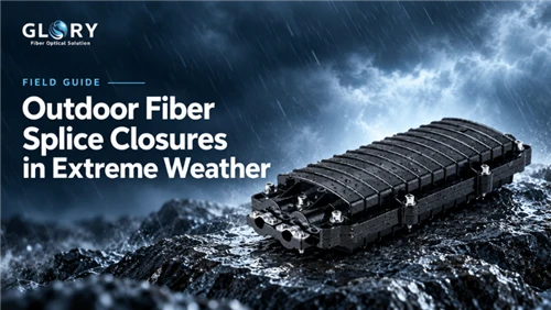
Weather resistance at the installed joint
An outdoor fiber splice closure protects the splice only when its housing, seals, cable anchors and accessories work together. A sound-looking shell can conceal a leaking cable entry or a strained fiber tray. Weather resistance therefore depends on the installed assembly, including the cable and workmanship, as well as the product's qualified performance.
Exposure varies by location. An aerial closure faces wind and sunlight; a flooded handhole puts every cable entry underwater. Coastal sites combine salt, heat and moisture, while mountain routes face ice and repeated freezing. This guide explains how those conditions affect a joint and what engineers and buyers should check before installation and after a storm.

On this page
- Weather resistance at the installed joint
- 1 How the closure protects the splice
- 2 Heavy rain and prolonged flooding
- 3 Lightning and metallic cable components
- 4 Wind cable movement and mechanical restraint
- 5 Snow ice and repeated freezing
- 6 Solar heat and ultraviolet aging
- 7 Salt moisture and coastal corrosion
- 8 Choosing a closure for the installation
- 9 Reviewing environmental test evidence
- 10 Inspection and restoration after severe weather
- 11 Frequently asked questions
1 How the closure protects the splice
A typical closure contains a protective housing, a main body seal, cable-entry seals, anchors and splice trays. Dome and horizontal designs can both serve outdoor routes. Their suitability depends on the sealing system, approved accessories and installation configuration. Body shape alone does not establish waterproof performance.
The shell resists physical exposure, while its material and geometry influence impact behavior, aging and deformation. The main gasket must stay clean and correctly compressed after handling and reopening. Entry seals must fit the actual cable diameter and profile. A test performed with one cable configuration may not establish compatibility with another.
Cable anchors and strength-member clamps should take external forces before they reach bare fibers or splice protectors. Trays maintain bend routing and keep service loops clear of the body joint. During assembly, inspect the complete force path and sealing path: neat trays cannot compensate for an incorrect entry insert or missing port plug.
| Component | What it protects against | What to check |
|---|---|---|
| Housing and body joint | Impact, rain, external exposure | Cracks, warping, gasket seating |
| Cable ports and plugs | Water entry at cable interfaces | Actual cable OD, profile, correct inserts |
| Cable anchors | Pull, vibration and movement | Strength-member termination and strain relief |
| Splice trays | Bending and accidental contact | Bend routing, slack and tray closure |
| Mounting hardware | Wind and suspended loads | Bracket, bolts, corrosion and support |
2 Heavy rain and prolonged flooding
How water enters the joint
Wind-driven rain loads exposed seals from different directions. In a flooded chamber, the whole closure may remain immersed while drainage is blocked. Wet soil adds prolonged moisture exposure and potentially changing water pressure. Identify which condition the site will face before selecting the enclosure or interpreting its ingress rating.
Common leakage paths include a pinched gasket, grit on the mating surface, an insert that does not fit the cable profile, and an incorrect blanking plug. Reopening can contaminate or damage a seal. Cable movement after installation can also disturb the entry interface, particularly when its restraint is inadequate.
Water may travel through a damaged cable jacket or along the cable construction, depending on its water-blocking design. A wet splice chamber therefore calls for investigation of both the enclosure and the cable. Trace the entry path before deciding which component needs replacement.
Interpreting an IP68 claim
IEC 60529 defines enclosure ingress-protection categories. The second digit 8 identifies immersion protection under specified conditions. The IP68 mark does not, by itself, state an unlimited depth, indefinite exposure time or compatibility with every cable arrangement. Obtain the declared IPX8 conditions from the supplier or test report.
Check the tested depth and duration, cable sizes, occupied ports, blanking accessories and assembly procedure. Compare them with the planned installation. For a joint that will be reopened, also ask whether sealing performance was evaluated after re-entry and resealing. These details make the rating useful for a procurement decision.
Confirm whether the model is approved for chamber mounting, direct burial or both. Direct burial introduces soil pressure and installation damage as well as moisture. Support the joint and its cables so their weight or external tension does not load the sealing interfaces unnecessarily.
Installing and checking the seals
Clean the mating surfaces and inspect elastomers for cuts, flattening and contamination. Measure the cable at the sealing location, use the approved inserts, and follow the manufacturer's compression or torque procedure. Install the cable anchors before closing the body so an external pull cannot load the tray or disturb the entry seal.
Use the manufacturer's leak or pressure check where the model supports one. Photograph the completed port arrangement and retain the record. During maintenance, keep the open closure clear of standing water and replace seals that are not reusable. Restoring the documented assembly procedure matters more than simply drying the housing and closing it again.

3 Lightning and metallic cable components
Glass fiber does not conduct current like copper, but an optical cable may contain metal armor, a messenger or strength members. Supporting hardware can also be conductive. These elements change the lightning risk. A plastic splice closure is an environmental enclosure, not a lightning arrester or proof against a direct strike.
A direct flash can damage a line or its support structure. Nearby lightning can create electrical stress and potential differences, while continuous metal components may carry effects beyond the flash location. An intact housing does not establish that the surrounding metal hardware or connected equipment escaped damage.
ITU-T K.47 addresses protection of telecommunications lines against direct lightning flashes. Assess the cable construction and route exposure as part of the network design. Selecting a closure is one part of that work; it cannot replace a coordinated protection scheme for the line and associated equipment.
Armor continuity bonding and grounding
Determine whether the cable is all-dielectric and identify every conductive element. Under the operator's approved design, metal parts may need continuity, isolation or bonding at the joint. Those arrangements serve different purposes. Changing a connection or adding an earth connection without understanding the system can introduce hazards.
The approved scheme may include coordinated bonding and earthing, separation from electrical hazards, route planning and protection at equipment interfaces. Shared power and communications structures also require attention to local installation rules. Trained personnel should implement the scheme. Closure termination points only support the prescribed arrangement.
Ask for a drawing showing the permitted treatment of armor and metal strength members. If a supplier claims lightning resistance, identify what was tested: a material, a particular isolation feature or a complete assembly. A general claim without a defined configuration gives a buyer little basis for selecting the joint.
Inspection after lightning
Approach a damaged line only after the site and supporting infrastructure are declared safe. Look for burned jackets, melted parts, damaged mounts and unusual discoloration, then localize the optical fault using the normal test procedure. Normal splice loss does not prove that the electrical protection system is still safe.

4 Wind cable movement and mechanical restraint
Wind moves aerial cables, and the resulting loads depend on span, sag and support geometry. A poorly supported closure can swing or rotate, transferring movement into its cable ports. Repeated small movements can undermine an inadequately restrained interface even when the shell remains undamaged.
Trace the load from the hanger or bracket through the cable anchors. The mount carries the closure; the anchors restrain the jacket and specified strength elements. Fibers and splice protectors must remain free of structural loads. Inspect for rubbing, loose supports and unmanaged service loops that can catch wind.
Flying debris, branches and driven rain add to the exposure. Check impact suitability together with pole bands, bolts, corrosion and the mounting surface. For a severe-wind route, evaluate the mounted assembly against the operator's construction requirements rather than relying on a rugged-housing claim alone.
5 Snow ice and repeated freezing
Ice adds weight to aerial cable and hardware and can change line tension. Moisture trapped around a joint may freeze, while daily temperature changes repeatedly move its components. Plastics, metals and elastomer seals contract differently, so the complete cable-populated assembly must suit the intended cold-weather environment.
Subzero conditions do not automatically cause a qualified seal to fail. Risk increases when the exposure exceeds the design assumptions, a seal is damaged or an interface is assembled incorrectly. Winter handling can also damage a component whose material has become less tolerant of impact.
Check internal slack and bend routing so movement outside the closure cannot pull fibers into sharp bends. Where winter access is necessary, protect the open joint from snow and moisture. Follow installation temperature restrictions and the instructions for inspecting or replacing seals before reclosure.
For cold-region procurement, request temperature-change results and the optical, mechanical and sealing acceptance criteria. An operating-temperature range alone does not explain how the populated closure was assessed. IEC 61300-2-22 provides a temperature-change test method for relevant fiber-optic devices and passive components; the applicable product specification still determines the test conditions and limits.
6 Solar heat and ultraviolet aging
Direct sunlight can heat a closure surface above the surrounding air temperature. Solar radiation, material, color, wind and mounting position affect that rise. Daily expansion and contraction continue over years, while stiffening seals, fading or embrittlement may develop gradually and become apparent during maintenance.
Ask how outdoor polymers and elastomers were qualified for the intended exposure. Material data can help explain the design, but distinguish it from tests on representative components or complete assemblies. Seals need to retain the resilience required to maintain contact pressure as the product ages.
Inspect aged seals and mating surfaces before reopening and reclosure. Replace parts where the manufacturer's instructions require it. Forcing a warped or contaminated lid shut does not restore the original sealing configuration. Keep internal cable routing within the specified bend limits, even when additional slack or trays are needed.
7 Salt moisture and coastal corrosion
Salt-laden air and persistent humidity expose brackets, bolts and fittings to corrosion. The polymer body may look sound while metal hardware deteriorates. A corroded fastener can reduce mounting security or make maintenance difficult even when the splice chamber remains dry.
Request material grades for external hardware and review contacts between dissimilar metals. When a salt-spray report is cited, identify the tested parts, method, duration and acceptance criteria. Exposure hours without those details do not predict a universal field service life.
Coastal selection should address the combined exposure: corrosion of hardware, rain at seals, solar aging and wind-driven cable movement. Tests help evaluate individual properties, while accessible mounting and routine inspection help identify deterioration in service. Match both the materials and the maintenance arrangement to the site.
8 Choosing a closure for the installation
Splice capacity defines the fiber-management arrangement, while environmental qualification defines the exposure the assembly has been assessed for. Review both, together with the actual cable interfaces and mounting kit. A capacity figure alone gives little guidance for choosing between a flooded chamber and a windswept pole.
| Location | Dominant exposure | Priority checks |
|---|---|---|
| Aerial pole / messenger | Wind, UV, rain, lightning environment | Mounting, anchoring, cable metal design |
| Underground handhole | Flooding, sediment, re-entry | Declared immersion conditions, entry seals |
| Direct-buried joint | Moisture, soil contact, mechanical pressure | Explicit direct-burial suitability |
| Mountain / cold region | Ice, cold, freeze–thaw | Low-temperature function, cycling tests |
| Tropical outdoor site | Rain, humidity, solar heat | Sealing, material aging, maintenance |
| Marine / coastal | Salt, humidity, wind | Fastener materials, corrosion evidence |
For a coastal aerial route, give close attention to mounting, restraint, UV suitability and exposed metal hardware. For a low-lying handhole, prioritize the declared immersion conditions, entry configuration and resealing procedure. Two closures with the same fiber capacity may require very different qualification evidence for those locations.
Compare dome and in-line models using their documented construction and application. Request the exact model drawing, cable-port matrix, accessory list, installation guide and relevant test results. Confirm that the quoted revision and intended cables match the configuration being evaluated.
9 Reviewing environmental test evidence
A useful report identifies the sample, its cables and accessories, the test procedure, exposure conditions and result. This connects a product claim to a configuration that can be reproduced. Read the report with the installation guide so field assembly can follow the arrangement that was assessed.
For immersion, check the declared conditions. For cable retention, review the force and any optical or sealing defect afterward. For thermal cycling, examine limits, dwell periods and post-test checks. Salt and UV reports should identify whether the tested item was raw material, a component or a complete assembly.
A test method defines a reproducible procedure; the applicable specification defines acceptance. Passing one program does not establish performance with a different cable profile, greater water pressure or repeated maintenance over many years. Resolve those differences before qualification rather than assuming a broad claim covers them.

| Evidence to request | Why it matters |
|---|---|
| Exact model and revision | Avoids applying another model's claims |
| Cable diameter / port configuration | Seals depend on the installed geometry |
| IP test conditions | Defines what immersion claim means |
| Temperature-change report | Links ambient limits to test evidence |
| Pull / torsion / impact results | Connects hardware to field loads |
| Seal reuse / re-entry instructions | Supports consistent maintenance |
| Material / corrosion declaration | Screens coastal hardware risks |
10 Inspection and restoration after severe weather
Make the site safe before entry or access. Flooded pits, damaged poles and suspended lines can present electrical, atmospheric and structural hazards. Follow the operator's electrical-safety, site-entry and confined-space procedures before inspecting the joint.
Review when the fault appeared and which customers or branches were affected. Compare alarms with route maps and earlier test records. A problem confined to one branch calls for a different investigation from a feeder fault affecting many customers, and delayed symptoms may warrant reviewing earlier weather exposure.
Photograph the surroundings before opening the closure: supports, entries, waterline marks and damaged jackets. Follow the approved disassembly procedure, then inspect for displaced seals, sediment, water marks, corrosion and strained trays. A port defect may leave the main housing apparently intact.
Use an optical loss test set to compare link insertion loss with the agreed baseline and acceptance plan. Use an OTDR to help locate events along the route. Neither measurement proves water ingress on its own. Combine optical findings with physical inspection before identifying the cause.
Correct the cable and sealing arrangement that failed, using permitted cleaning or replacement parts. Then restore and verify the assembly as required by the manufacturer and project procedure. Record photographs, replaced parts and before-and-after measurements. Drying the chamber alone leaves an incorrect insert or loose anchor unresolved.
11 Frequently asked questions
Q: Suitability for several days underwater
A: Compare the expected depth and duration with the declared IPX8 conditions. Also verify the cable arrangement, seals and approved installation type. The IP68 marking alone does not answer the duration question.
Q: Protection against a direct lightning strike
A: A plastic shell is not a certified lightning-protection system. Assess the route's conductive elements, supporting structures, bonding design and equipment protection together with the closure.
Q: Leakage without a cracked housing
A: Investigate the gasket, cable insert, clamping arrangement, sealing-surface contamination and unused-port plugs. Any of these can create a water path while the body remains intact.
Q: Optical loss during freezing weather
A: Ice loads and temperature-related movement can strain an unsuitable or poorly installed joint. Localize the impairment with optical tests and inspect the assembly before attributing it to the weather.
Q: Replacement after a flooded chamber
A: Replacement depends on ingress, damage, contamination, corrosion and the manufacturer's recovery instructions. A joint that can be properly restored and verified may remain serviceable; normal optical transmission alone is insufficient.
Q: Selecting and verifying the complete joint
A: Select the closure, seals, cable interfaces and mounting arrangement for the actual site. Install them using the approved procedure and retain records that allow the joint to be checked after maintenance or severe weather. This gives network owners a practical basis for preventing leakage and mechanical faults without overstating what an enclosure can protect against.