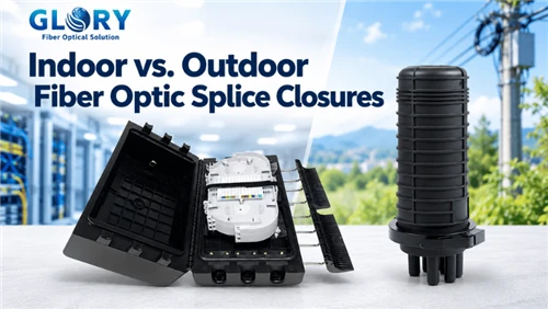
Indoor vs. Outdoor Fiber Optic Splice Closures
At first glance, an indoor splice enclosure and an outdoor fiber optic splice closure perform the same job: they protect spliced fibers, maintain orderly routing, and preserve access for future work. The difference becomes consequential only when the surrounding environment begins to act on the cable joint. Water can track along a poorly sealed cable, sunlight can age housing materials, and routine reopening can disturb a once-reliable interface.
In this guide- 1. Start with the installation environment-not the enclosure name
- 2. What both enclosure types must protect
- 3. Enclosure anatomy: where the differences actually appear
- 4. Water, humidity and condensation
- 5. Temperature, ultraviolet light and material aging
- 6. Mechanical loads and cable retention
- 7. Splice capacity is only one part of capacity planning
- 8. Sealing mechanisms and repeated access
- 9. Indoor placement: accessibility, fire rules and building interfaces
- 10. Outdoor placement: aerial, handhole and direct-burial decisions
- Indoor vs. outdoor: the practical comparison
- 12. Procurement checklist: what to ask before ordering
- 13. Final decision guide, FAQs and references
The useful purchase question is therefore not simply "indoor or outdoor?" It is "what stresses will this joint experience during installation, normal operation, and its next maintenance visit?" This guide compares the two approaches and offers a site-specific method for specifying the right equipment.
an equipment-room panel, a pole-mounted dome closure and a handhole enclosure are not interchangeable products. Yet their differences cannot be inferred from shape, color, capacity, or IP rating alone.
1. Start with the installation environment-not the enclosure name
"Indoor" describes a location, not a guarantee of stable conditions. A climate-controlled telecom room is different from an unheated building basement, an open parking garage, or a utility shaft exposed to leaks. Likewise, "outdoor" covers several distinct hazards: sunlit pole installations, sheltered cabinets, roadside handholes, and burial below grade. These sites impose different combinations of moisture, UV exposure, temperature cycling, mechanical loading, and accessibility.
Consider a closure in a basement immediately below a street-level cable entry. The unit sits technically inside the building, but groundwater seepage and condensation may be more relevant to product selection than its address. Conversely, an outdoor-rated closure mounted inside a secure, dry plant room may add unnecessary size and installation complexity unless a specific project requirement justifies it.
IEC 61753-1 defines environmental performance categories across controlled indoor and outdoor conditions. For sealed closures, IEC 61753-111-07, -08, and -09 focus respectively on aerial, ground, and subterranean categories. This distinction is more actionable than a broad "outdoor suitable" description.

2. What both enclosure types must protect
A splice enclosure is not merely a container for fusion splice protectors. At minimum, it must preserve fiber routing, provide controlled storage of spare fibers, prevent unsupported cable movement from reaching the splices, and allow technicians to identify and service circuits. The mechanical interfaces often matter more than the visible shell.
Fiber is fragile when subjected to localized bending, crushing, or inadvertent pulling at a splice. A strain-relief arrangement should secure the cable jacket and, where relevant, strength members before the fibers are routed to a tray. A neat tray layout that lacks real cable retention can still fail after a cable is tugged during a later installation.
Indoor facilities commonly favor front access, rack or wall compatibility, readable labeling, and orderly patching or splicing. Outdoor plant adds protection from water, debris, weather, and mechanical movement. Those differences are matters of priority, not a license to neglect fiber management indoors.
The enclosure is a system
- Outer body and lid: protect the fiber-management space.
- Cable entry components: adapt the enclosure to each cable diameter and geometry.
- Strength-member anchoring and jacket clamps: isolate the splice area from cable loads.
- Splice trays and slack storage: maintain safe routing during normal operation and maintenance.
- Mounting hardware and closure process: preserve protection after installation and re-entry.
IEC 61756-1:2019 provides guidance for fiber-management interfaces and identifying minimum bending radius of stored fibers; it does not replace cable-entry sealing requirements.
3. Enclosure anatomy: where the differences actually appear
An indoor wall-mounted enclosure may use a hinged door, removable cover, cable glands or grommeted openings, and compact splice trays. The installation is often accessed from the front, and the technician expects to work close to other building services. The accessible face, working clearance, and route to surrounding equipment can be just as important as the tray capacity.
An outdoor closure generally depends on a deliberately controlled sealing path around the body joint and every cable entry. Dome-style enclosures typically place cable entries at one end. Inline designs typically accept cables through opposed ends, favoring through-route configurations. The arrangement should match network topology, but neither form factor alone proves a particular environmental rating.

4. Water, humidity and condensation
Outdoor rain is the obvious water source, yet it is not the only failure mode. Water can collect in underground access chambers; moisture can condense during repeated warming and cooling; and a cable that is not correctly matched to its gland may create a path into an otherwise well-made body. Problems may appear months after commissioning, particularly when additional cables are installed.
For a climate-controlled indoor room, environmental sealing may play a secondary role to access and routing. For a damp basement or handhole, sealing becomes a defining requirement even if the installation is nominally "inside" or sheltered. The site survey should record whether there is occasional spray, persistent humidity, standing water, or credible submersion.
How to interpret IP ratings
IEC 60529 provides the IP-code framework. An IP68 claim indicates specified protection against dust and immersion under stated test conditions; it is not a universal promise of permanent service under any depth, duration, pressure, cable combination, or maintenance history. Ask the supplier for the immersion conditions and a report applicable to the installed cable entries and assembled configuration.
The practical failure point is often the complete seal system rather than the plastic body. Incorrect cable sizes, blanking plugs removed without approved replacements, contaminated gaskets, or poorly seated seals can defeat laboratory performance.
5. Temperature, ultraviolet light and material aging
A pole-mounted closure may experience daytime solar heating and rapid night cooling, rain after a hot afternoon, or winter freeze-thaw exposure. The housing, seals, clamps, and cable jackets respond differently to repeated expansion and contraction. Over time, the relative movement can challenge marginal cable-entry arrangements and mounting systems.
UV resistance is most relevant where the housing sees direct sunlight. A dark polymer housing is not automatically UV-stable simply because it is black; pigment, stabilizers, formulation, manufacturing quality, and validated testing all matter. Outdoor claims should therefore be supported by a defined material or product test rather than appearance.
Indoor enclosures still face thermal and fire-related considerations. A telecom room adjacent to active electrical or electronic equipment may be warmer than an office. In a building, the material selection and placement may also depend on local fire and cable-installation requirements. "Indoor" should not be presented as synonymous with "flame-retardant"; the applicable fire rating must be established separately for the exact product and installation.
What the engineer should request
- Declared operating temperature range and supporting test method.
- Weathering or UV test results for exposed outdoor installation.
- Sealing performance after relevant thermal and mechanical testing.
- Housing material, gasket material, and replacement-part availability.
- Applicable building fire performance evidence, when required.
6. Mechanical loads and cable retention
A splice closure must not allow ordinary cable movement to act directly on the splice sleeves. Outdoors, the sources include wind-induced movement of aerial spans, tension at poles, pull forces during duct work, vibration, and movement at handholes. Indoors, technicians may tug adjacent cables or shift bundles during equipment upgrades. Different sources, same potential consequence: uncontrolled force transmitted to buffered fibers.
Cable clamps, strain-relief fixtures, and strength-member anchors need to suit the installed cable. Flat drop cable, round loose-tube cable, and microcable do not necessarily use interchangeable seals or clamping inserts. A port count on a datasheet describes a maximum layout, not the set of cable profiles that may safely be installed at the same time.
Cable retention should be verified at the complete assembly level. Where a supplier quotes pull, torsion or bend tests, request the tested cable diameter, cable type, sample configuration and acceptance criteria. Avoid copying one product family's pull value into another family without proof.
For aerial projects, inspect hardware compatibility, mounting orientation, wind exposure, and the route of the cable as it approaches the closure. For buried work, check crush exposure, handling during excavation and possible soil or water movement. Hardware should not be selected only by the nominal capacity of the fiber tray.
A worked capacity example
Suppose a feeder cable of 96 fibers enters a neighborhood distribution point. The immediate work order calls for 48 splices, but the route must preserve the remaining fibers for downstream expansion. A closure advertised as "96 cores" might provide enough splice positions, yet it can still be unsuitable if the trays do not segregate active and reserved fibers, the pass-through tubes cannot be stored without tight bends, or the required branch cables exceed the available sealed ports. A capacity review should therefore account for active splices, express fibers, future drops, tray allocation, and the routing path between entries-not just the largest number in the product title.
A useful acceptance exercise is to request the proposed tray-loading drawing for the real cable schedule. Show the number of fibers per tube, the location of splitters if any, and the slack required for a technician to lift and work on one tray without stressing adjacent circuits. This turns an ambiguous "96F" specification into an inspectable assembly plan.
7. Splice capacity is only one part of capacity planning
A specification such as 48, 96, 144 or 288 fibers says little about day-two maintenance if the enclosure lacks usable access or slack-storage space. Distinguish between maximum splices under a particular tray configuration and the capacity that works with the project's cable count, splitter layout, splice method, and required spare fibers.
Take a 96-fiber distribution branch as an illustrative design exercise. The buyer should calculate not only 96 potential splices but also the number of feeder and branch cables, the maximum outside diameter at each port, the number of live fibers requiring safe separation, storage for uncut buffer tubes, and room for future changes. A unit with "96-core capacity" may be poorly suited if its port arrangement cannot accommodate the actual route.
Indoor environments often make visual circuit identification and front access decisive. Outdoor enclosures commonly demand careful management of uncut cable, separated work zones, and tray access without disturbing live fibers. That does not make either category universally more sophisticated. The network's topology and maintenance plan determine the required architecture.
IEC 61756-1 is a useful technical reference when evaluating the fiber-management arrangement. Designers must also respect the requirements of the actual fiber, cable and splice-protection components rather than assuming a single universal coil diameter.
Heat-shrink versus mechanical sealing
Heat-shrinkable cable entries can provide a robust fit when installed with the correct sleeve, preparation and heating procedure. They can also make later cable additions more involved, depending on the design. Mechanical or gel-based arrangements may simplify opening and modification, but require the correct cable inserts, closures, compression sequence and clean sealing surfaces. Neither technology is automatically superior; the right choice depends on the planned number of interventions, operator skill, available tools and approved accessory kits.
For a deployment expecting frequent additions, specify a re-entry demonstration using the actual cable mix. The technician should reopen the unit, introduce the additional cable, restore the seals and verify the closure according to the manufacturer's procedure. A first-assembly laboratory rating is valuable, but this field sequence is closer to how the asset will be used.
8. Sealing mechanisms and repeated access
Heat-shrink, mechanical gasket, gel and gland-based sealing systems offer different installation workflows. Heat-shrink may involve a controlled heating process and consumables. Mechanical and gel systems may provide simpler re-entry when approved components are reused according to instructions. The better choice depends on field tooling, contractor training, weather conditions, service frequency, and the cable range.
A seal that works on the first day is insufficient if the network will be modified regularly. Opening a closure can expose the gasket to sand, grease or fiber scraps; it can also alter cable routing or unset a clamp. After an intervention, the site crew needs an explicit inspection and resealing process. Replacement inserts, blanking plugs and spare glands should be available before the work begins.

A useful RFQ question is not simply "Is it re-enterable?" Ask whether re-entry has been tested, how many cycles are covered by the evidence, which items must be replaced, what cable configurations were used, and whether sealing is rechecked after each cycle. Answers that identify exact accessories and procedures are more valuable than general marketing terms.
The indoor-to-outdoor transition
A building entrance is often the point at which an otherwise sound splice plan becomes difficult to operate. The incoming OSP cable may need to be transitioned, terminated or routed under building cable rules; the enclosure must sit where technicians can reach the trays without disturbing other services. The design should document the entry sleeve or conduit, cable restraint on both sides of the interface, identification of incoming and outgoing cables, and any required bonding or grounding for metallic elements. A sealed outdoor closure placed in an electrical room does not by itself resolve these building-interface obligations.
For multi-dwelling units, distinguish the feeder-splice function from subscriber distribution. A compact wall box may be better for a handful of drop splices and routine access, while a larger protected assembly may be needed for the feeder route or humid service shaft. Splitting the functions can improve maintainability if the architecture and space allow it.
9. Indoor placement: accessibility, fire rules and building interfaces
A building installation raises concerns that are less visible in an outdoor product catalog. Is the enclosure positioned so a technician can open it without removing other equipment? Will cable slack remain separated from electrical services? Can the route pass through a wall or floor without compromising a required firestop? Can the box be labeled and inspected by a later contractor?
The distinction between a splice enclosure, patch panel, termination box, building-entry point and distribution frame is also important. An indoor splice enclosure should not automatically be specified for tasks requiring accessible connectorized patching. Conversely, using a patching product as a substitute for a sealed outside-plant joint may expose a protected network segment to unnecessary vulnerabilities.
At building entry, outdoor cable transitions and local fire and cable rules may affect where equipment belongs and how cables are routed. Requirements vary by jurisdiction and building type, so a global buying guide should flag the issue without claiming that one distance or flame rating applies everywhere.
Installation notes worth including on the drawing
- Mounting height and door-swing/cover-removal clearance.
- Incoming and outgoing cable routes, minimum bending envelope and support.
- Firestopping and segregation requirements at building penetrations.
- Labeling and circuit identification for day-two maintenance.
- Potential sources of condensation, leakage and unauthorized access.
Case: pole-mounted branch closure
At an aerial branch point, check more than rain protection. The mounting bracket must suit the pole or strand, the cable approach should avoid tight turns at entry, and the hardware should not transmit unnecessary span loads to the sealed ports. Cable entry orientation, available working space at height and the ability to add a branch safely all affect the installed result. An aerial-category performance claim and compatible mounting kit are more persuasive than a generic "outdoor" label.
Case: roadside handhole
In a handhole, the risk profile changes. Standing water, grit, cable movement during chamber work and limited space for reopening may dominate. The assembly should be evaluated for the relevant ground or subterranean service conditions, not merely selected because it survived a rain-spray test. Confirm the intended mounting position, cable loop arrangement, chamber clearances and applicable immersion conditions before installation.
Case: direct burial
Direct burial is not the same as putting a standard pole closure under soil. Soil loading, backfill, long-term water exposure, the ability to locate and excavate the joint, and project-specific mechanical protection all become material. Unless a product is explicitly qualified and instructed for direct-burial use, design a suitable accessible chamber or select a properly rated system instead of extrapolating from an IP number.
10. Outdoor placement: aerial, handhole and direct-burial decisions
Outdoor suitability should be assigned per placement. A pole-mounted closure is exposed to UV, driving rain, motion and hardware loading. A handhole closure may face repeated flooding, sediment, restricted working clearance and handling while crews move other cables. Direct burial adds soil loading, excavation risk and potentially prolonged moisture exposure. A sheltered cabinet reduces some weather stresses but can still experience condensation and temperature swings.
IEC 61753-111-07:2021 addresses sealed closures for category A aerial exposure; IEC 61753-111-08:2021 covers category G ground; IEC 61753-111-09:2021 concerns category S subterranean conditions. Their use is more precise than declaring every IP68 enclosure suitable for every outdoor arrangement.
The site-specific decision should include a drainage and flooding assessment, accessible mounting orientation, strain relief, cable approach, available work space, and likelihood of repeated entry. If equipment sits in a chamber that may be submerged, the submersion exposure and installed sealing configuration must be checked with the supplier, rather than assuming that any immersion test settles the question.
When assessing direct burial, check whether the model is explicitly approved for that installation method, not merely for a nearby underground handhole. Civil works, protective ducts and local practice may also change the product requirements.
Indoor vs. outdoor: the practical comparison
| Decision factor | Indoor-controlled placement | Outdoor or exposed placement |
|---|---|---|
| Main risk | Access, routing, building requirements | Moisture, UV, mechanical loads |
| Sealing | Dependent on location | Critical at body and cable interfaces |
| Mounting | Wall, rack, cabinet | Pole, strand, pedestal, chamber |
| Cable entry | Organized routing and restraint | Sealed profile-specific entry and retention |
| Re-entry | Service access, labeling | Repeatable sealing and access |
| Evidence | Building suitability and mechanical fit | Environmental-category and assembly test evidence |
Treat this comparison as a screening tool, not a hard technical boundary. An indoor basement may require an outdoor-style moisture barrier; a fire-rated outdoor closure may serve a building-specific role; and a high-capacity indoor panel may be larger than a compact aerial closure.
Three example specifications
Example A - dry MDF room: prioritize rack/wall footprint, splice-tray accessibility, labeling, restraint and required building fire properties. High immersion performance may not be the main cost driver.
Example B - pole-mounted FTTH branch: prioritize cable profiles, branch ports, UV/weather performance, mounting and the tested sealing system. Dome or inline geometry follows topology, not the word "outdoor".
Example C - periodically flooded handhole: prioritize documented water exposure conditions, sealing after re-entry, cable retention, mounting clearance and service procedures. "IP68" without test conditions is incomplete information.
A sample technical request for quotation
The following specification language is more useful than "outdoor splice closure, 144F, IP68": "Provide a re-enterable sealed fiber optic splice closure suitable for a roadside handhole with intermittent standing water. Accommodate one 12 mm round feeder, two 8 mm distribution cables and four 2 × 3 mm flat drops using listed port accessories. Supply a port-allocation drawing, tray-loading plan, cable-retention method, operating-temperature declaration, immersion-test conditions, and assembly instructions for the exact combination. Confirm test reports relevant to the required environmental category and demonstrate resealing after a planned cable addition." Cable sizes and counts here are illustrative; the real RFQ must use the project cable schedule and vendor-approved ranges.
For bid evaluation, score submitted evidence separately from claimed features. "IP68" without a test configuration, "144F" without tray drawings, and "re-enterable" without an approved service procedure should be treated as incomplete responses, not necessarily as failed products. Request clarification before assigning technical compliance.
12. Procurement checklist: what to ask before ordering
The best RFQ states the environment and the assembled cable system before naming the enclosure model. Otherwise suppliers may quote visually similar products that differ on the interface details responsible for installation failures.

- Site: dry indoor, damp indoor, exposed aerial, cabinet, flooded handhole or direct burial?
- Cable schedule: fiber count, jacket profile, outside diameter and strength-member design for each entry?
- Topology: through-route, mid-span access, branching or distribution?
- Capacity: splice type, tray count, slack storage and future service margin?
- Sealing: approved grommets, inserts, heat-shrink sleeves or gel parts for each exact port?
- Evidence: reports, edition and scope of the stated test standard, IP conditions where claimed?
- Maintenance: access, re-entry instructions, consumables, spares and resealing method?
- Mounting: required orientation, brackets, space envelope and retention hardware?
Ask the supplier to return a configuration-specific bill of materials. It should identify the body, tray pack, cable seal for each diameter, blanking items, strain-relief accessories and mounting kit. A headline closure price without this accessory set is rarely an apples-to-apples comparison.
13. Final decision guide, FAQs and references
Choose the splice enclosure that matches the actual exposure of the installed joint and its expected service life. In a dry equipment room, efficient access and compliant building integration may dominate. On a pole, exposure and retention dominate. In a wet handhole, reliable sealing and repeatable maintenance become decisive. Across all three, fiber routing and cable-interface compatibility remain non-negotiable.
Frequently asked questions
Can an outdoor splice closure be used indoors? Often yes from a fiber-protection standpoint, but verify the exact product's size, access method, material/fire properties and local building requirements. Outdoor suitability is not a substitute for building compliance.
Can a typical indoor splice box be installed outdoors? Not without evidence that it meets the actual exposure. A roofed location may still see condensation, dust, wind-driven rain or temperature changes.
Is IP68 required for every outdoor splice closure? No single IP number alone determines suitability across all aerial, cabinet and buried applications. Specify the relevant environmental and deployment requirements, then verify test evidence.
Is a dome closure better than an inline closure? Neither is universally better. The cable route, branch pattern, mounting envelope, service plan and verified test performance determine the fit.
Do indoor closures need cable strain relief? Yes. Cable movement and maintenance activity can damage internal fibers in any location.