How to Test Fiber Optic Fast Connectors Before a Bulk Order
A trial should tell you whether a specific connector, cable and installation process can meet your project's optical and labor requirements. Use this fiber optic fast connector testing checklist to set the rules before sampling, record each unit, and decide whether the results support a bulk purchase.
Here, fast connector means a prepolished fiber stub with an internal mechanical splice, often sold as a quick connector or cold connector. Field-installable connectors also include other termination designs. Follow the instructions for the exact SKU being tested.
In this guide- Set the trial scope and acceptance rules
- Choose a representative sample and sample size
- Record units, attempts and measurements
- Run the trial with the project crew and tools
- Measure connector insertion loss and return loss
- Investigate failures and control rework
- Calculate yield and apply the purchase rules
- Request evidence for long-term performance
- Frequently asked questions
Before the first termination
- ✓Confirm the connector SKU, production batch, cable compatibility and installation instructions.
- ✓Agree on the sample size, sampling method, IL/RL limits, allowed failures and rework limit.
- ✓Define the connector measurement boundary, reference setup, wavelengths and equipment.
- ✓Separate training units and exploratory stress tests from the qualification sample.
- ✓Assign a unique unit ID and retain every attempt, failed unit and measurement record.
- ✓Report first-pass yield, final yield and the statistical bound separately before making the purchase decision.
1. Set the trial scope and acceptance rules
The mechanical splice inside a fast connector makes fiber preparation and insertion part of its optical performance. The Fiber Optic Association's guide to prepolished/splice connectors describes the combined connector and splice loss, and explains why tools, training and installed yield affect the economics.
A datasheet provides a starting specification. A field trial measures the result of the selected product and installation process under the conditions you plan to use. Have the buyer, supplier and technical reviewer agree on the following items before opening the qualification sample.
| Plan item | Required agreement |
|---|---|
| Product and batch | Exact SKU and revision, APC or UPC interface, batch codes, and the population the sample represents. |
| Project cable | Fiber type, buffer and jacket dimensions, cable retention arrangement, and compatible tools. |
| Crew and conditions | Operators, prior product experience, locations and environmental conditions, with planned allocation of units. |
| Sample rules | Planned n, random selection method, failure definition, allowed failure count, and any pre-agreed second-stage sampling rule. |
| Optical measurement | Device under test, included interfaces, procedure, reference configuration, wavelengths, equipment IDs and reference checks. |
| Acceptance limits | Maximum per-unit IL, minimum per-unit RL, required first-pass yield, and the final-yield or confidence criterion. |
| Rework and retesting | Permitted actions, maximum re-terminations, cleaning/remeasurement rules and treatment of invalid measurements. |
| Decision and review | Who reviews the records, what permits procurement release, and how subsequent delivery batches will be checked. |
Write numeric limits as inequalities: IL must be at or below its maximum, and RL must be at or above its minimum. Keep the method attached to those limits. A value from a different measurement configuration may not be comparable.
For example, Glory's SC APC Fiber Quick Connector specification lists average IL ≤0.3 dB, maximum IL ≤0.5 dB and APC RL ≥55 dB. These are manufacturer specifications for that product. The average IL is a sample-level statistic; it does not mean every unit must meet 0.3 dB. Confirm the applicable test conditions and agree on your project limits.
2. Choose a representative sample and sample size
Select the units before inspecting their performance
Ask whether the samples come from the production batch intended for purchase. Samples selected for demonstration can establish cable fit or teach the installation process, but their results do not establish production-batch yield.
Select qualification units randomly from the defined batch or population. Include the operators and conditions that represent the planned work, with their allocation decided in advance. Keep deliberately difficult exploratory tests in a separate group. Combining them with the representative sample changes what the overall yield describes.
If several batches are included, retain batch-level results. A pooled figure cannot establish the performance of every batch. Outcomes can also cluster around an operator, tool or environment; review those patterns before treating a pooled binomial bound as a claim about routine deployment.
Use a confidence bound to interpret a small pilot
Here, n is the number of distinct connectors attempted and k is the number failing the defined endpoint. For independent binomial trials with a common failure probability, the exact one-sided 95% Clopper–Pearson upper bound limits the failure rate supported by the sample. NIST describes the exact binomial confidence-limit method.
| Distinct connectors (n) | 0 failures | 1 failure | 2 failures |
|---|---|---|---|
| 10 | 25.9% | 39.4% | 50.7% |
| 20 | 13.9% | 21.6% | 28.3% |
| 30 | 9.5% | 14.9% | 19.5% |
| 50 | 5.8% | 9.1% | 12.1% |
| 100 | 3.0% | 4.7% | 6.2% |
| 200 | 1.5% | 2.3% | 3.1% |
| 300 | 1.0% | 1.6% | 2.1% |
Calculated values, rounded to one decimal percentage point. These are mathematical examples, not Glory field results. With zero failures, the exact bound is 1 − 0.051/n; the familiar 3/n approximation is less accurate for small samples.
Ten clean units leave an upper bound of 25.9%, so that pilot cannot support a 99% yield claim. Under a pre-agreed rule requiring the final-failure upper bound to be no more than 5%, n=100 allows at most one final failure. This is an illustrative project rule, not a universal acceptance level.
Count failures twice for different purposes: first-pass failures before rework, and final failures after the permitted rework. Calculate each endpoint against the same distinct-unit denominator. Re-terminating one connector does not create another independent sample.
A qualification pilot and a contractual lot-acceptance scheme serve different decisions. If the contract specifies AQL, limiting quality or supplier/customer risk, use its sampling plan. NIST's acceptance-sampling guidance explains how sample size and allowed defects determine acceptance probability. Fix any staged sampling and stopping rules before collecting results.
3. Record units, attempts and measurements
Use one unit-register row per connector and a separate log row per measurement. Join them with the unit ID. Attempt 1 is the initial termination; each permitted re-termination increments the attempt number. A repeated optical reading on the same termination keeps that attempt number and gets a new reading number and measurement ID.
| Record | Fields to retain |
|---|---|
| Unit identity | Unique unit ID, exact SKU/revision, batch code and cable ID. |
| Cable construction | Fiber type, buffer and jacket dimensions, and the retention arrangement. |
| Installation conditions | Operator and experience, cleaver ID, blade position, environment and installation notes. |
| Measurement identity | Measurement ID, unit ID, attempt number, reading number, timestamp, wavelength and direction. |
| Measurement setup | Equipment and method IDs, reference lead and adapter IDs, and reference-check result. |
| Optical result | IL and RL in dB, measurement validity, and pass/fail at the agreed limits. |
| Rework and investigation | Failure code, action, number of re-terminations, and supporting notes or raw-file reference. |
| Unit outcome | First valid measurement on attempt 1, final reviewed measurement, and accept/reject/scrap disposition. |
Add a unit to the register when its initial attempt begins. Retain units that break, are abandoned or exceed the rework limit. An unmeasurable failed unit needs an incident reference and documented disposition. Training units belong outside the qualification register.
Preserve the first valid result even if later cleaning or rework improves it. If an equipment or reference fault makes a measurement invalid, retain that reading, the reason and reviewer approval, then take a replacement reading under the agreed procedure. Unresolved measurements remain pending.
The blank trial workbook retains the first and final measurement references for each unit and calculates the two yields. A reviewer checks all required wavelengths and directions before entering each unit outcome. Use a separate copy for each qualification run. The supplied calculation ranges cover 500 units and 1,500 measurement rows; extend them before exceeding those capacities.
4. Run the trial with the project crew and tools
- Give operators the current installation instructions and a separate practice allowance. Include typical crew members, with prior experience recorded.
- Check cable fit, stripping tools, cleaver condition and the specified cleave length before starting. Use the project cable and retention parts.
- Rotate the planned operator/tool/condition combinations so one person or time period does not account for an entire test group. Retain the pre-agreed allocation.
- Record each unit as it is prepared and each reading as it is measured. Follow the manufacturer's insertion and locking sequence.
- Keep failures and rework visible. If comparing with a reference termination method, record its units separately under comparable measurement conditions.
AFL's FASTConnect FAQ identifies cleave quality and fiber insertion as important troubleshooting checks, recommends a 10.5 mm cleave length, and allows up to five re-terminations subject to its stated restrictions. Those values apply to FASTConnect. Use your connector's current instructions and confirm any ambiguity with its supplier.
For the installation sequence itself, see the fast connector installation walkthrough. Measure preparation and rework time if the purchase decision depends on labor cost; yield alone does not capture all installation effort.
5. Measure connector insertion loss and return loss
Use the component measurement procedure agreed in the plan. A full-link loss reading includes other connections, fiber and splices. Comparing it directly with a connector datasheet limit can give the wrong verdict.
Define the test boundary and reference
Document which connector assembly, mechanical splice and mating interface the result includes. Identify the matching reference connector, leads and adapter. Keep the connector format and polish type compatible, and use the same approved reference arrangement throughout the run.
IEC 61300-3-4 describes component attenuation measurement methods; IEC 61300-3-6 describes return-loss measurement. Select the applicable procedure with the technical reviewer and supplier, including reference planes, launch conditions and uncertainty. A random-mating qualification needs its own applicable method.
Inspect, clean and take optical readings
- Inspect and clean the mating end faces under the selected procedure. IEC 61300-3-35:2022 covers end-face inspection and states that it does not replace optical performance measurement.
- Use a VFL as an installation aid where the product supports it. AFL describes it as a verification aid; it cannot provide an IL/RL acceptance result.
- Establish and verify the reference before measuring the DUT. Record the setup IDs and repeat reference checks at the agreed interval and after relevant setup changes.
- Measure IL and RL at every required wavelength and direction. A source-and-power-meter loss setup does not automatically measure RL; confirm the equipment and procedure provide the required return-loss result.
- Record the raw values and result. Apply the agreed handling of near-limit readings, invalid measurements and retests without replacing the original history.
IL is expressed as a positive loss value, with lower values preferred. Positive-dB RL is 10 log10(incident power/reflected power), with higher values preferred. OTDR event reflectance commonly uses negative dB, while whole-link optical return loss includes the link's combined reflections. Fluke's reflectance and ORL guide explains the distinction. Identify the reported quantity before comparing it with a per-connector RL limit.
If an OTDR forms part of the approved method, check event resolution, launch/receive leads and whether the DUT can be separated from neighboring events. The FOA installation guide explains why short links can be unsuitable for OTDR measurements. A visually clean end face or a link that carries traffic still needs the optical results specified in the trial plan.
6. Investigate failures and control rework
Use consistent codes to group investigation findings. The categories below are a suggested trial-log method. Symptoms can have several causes, so retain a provisional code until the evidence supports a diagnosis.
| Code | Observed symptom | Check first |
|---|---|---|
| C1 · Cleave quality | High IL or a damaged cleaved fiber end. | Blade position, cleanliness, preparation and suitable inspection evidence. |
| C2 · Cleave length | Fiber does not seat correctly or has an unsuitable bend. | Length gauge and exact product instructions. |
| C3 · Insertion | High IL despite apparently sound preparation. | Insertion depth, cable alignment and prescribed locking sequence. |
| C4 · Contamination | Unstable IL, visible debris, low positive-dB RL or elevated reflectance. | Both mating interfaces, cleaning, caps and reference stability. |
| C5 · Cable fit | Fiber or cable slips; retention is inadequate. | Supported cable dimensions and retention parts. |
| C6 · Tool/procedure | Failures cluster around an operator or tool. | Training, work instruction, cleaver and test equipment. |
| C7 · Suspected component issue | Failures cluster in one batch across operators and tools. | Returned units, batch handling, common test conditions and supplier examination. |
| C8 · Environment | Failures cluster in a site condition. | Dust, wind, temperature, lighting and working position. |
Hold a suspect batch for investigation when the agreed procedure requires it. A batch pattern is evidence to examine; confirming a component defect requires further checks. The unit, batch, tool and measurement records help distinguish competing explanations.
Re-terminate only within the product and project limits. AFL's FAQ includes an ST housing exception to reuse, which illustrates why a general reuse count is insufficient. Log the action, increment the attempt number and retest using the same acceptance method. A process change starts a separately identified run; retain the original results.
7. Calculate yield and apply the purchase rules
Use all distinct qualification units attempted as the denominator, including discarded and failed units:
- First-pass yield = units passing on the initial termination ÷ distinct units attempted.
- Final yield = units passing within the permitted rework limit ÷ distinct units attempted.
- Final failure count = distinct units attempted − final passing units, once every unit has a resolved outcome.
Report re-termination counts and, when collected, preparation/rework time alongside yield. A high final yield can still involve substantial labor. Pending outcomes prevent a complete qualification verdict.
Worked example: 98% final yield with two failed acceptance gates
These figures are invented for teaching and are not Glory test data. The buyer has agreed to test 100 units, require observed first-pass yield ≥95%, and require the one-sided 95% upper bound on final failure rate ≤5%.
| Measure | Result | Against the plan |
|---|---|---|
| First-pass units | 92 of 100 | 92% is below the required 95%. |
| Final passing units | 98 of 100 | Final observed yield is 98%. |
| Final failures | 2 of 100 | The exact upper bound is about 6.2%, above 5%. |
| Procurement action | Hold release under this plan | Investigate the failed gates before approving the product/process combination. |
The run misses both agreed gates. It does not by itself prove the connector batch is defective. Review operator, tool, environment and measurement patterns to decide what to investigate.
Use the pre-agreed outcome categories
| Outcome | Conditions | Action |
|---|---|---|
| Qualify | Complete records, valid comparable measurements, representative sample and all agreed gates met. | Document approval for the tested SKU, cable and process. Apply the agreed incoming-batch controls. |
| Pending | Missing/invalid readings, incomplete sample or unresolved record conflicts. | Resolve the gaps under the original plan. Keep the outcome open. |
| Investigate or do not qualify | A gate is missed or a recurring problem affects the planned use. | Review causes with the supplier. Use a separately planned run if the process or product changes. |
Do not add units repeatedly until a favorable fixed-sample bound appears. Use the staged design agreed before testing, or plan a new run with its own decision rule. Approval applies to the tested scope; subsequent batches and changed site conditions still need the controls recorded in the purchase agreement.
8. Request evidence for long-term performance
A short pilot addresses installation performance and immediate optical results. For long-term use, request evidence tied to the exact product revision: environmental and mechanical test conditions, duration, optical criteria before/after exposure, batch traceability and written warranty terms.
AFL states a 20-year shelf life for the gel in FASTConnect. Corning's LAN-848-EN white paper, published in 2007, discusses silicone-based index-matching gel reliability and cites material studies. Neither establishes the field lifetime of another manufacturer's complete connector.
The Glory SC APC product page lists 500 mating cycles, an operating range of −20 to +75 °C and a three-year warranty. Confirm the associated test conditions and warranty terms if these affect the project. A mating-cycle rating, warranty period and installed service life describe different things.
ITU-T L.404 covers field-mountable single-mode optical fiber connectors. Use the applicable recommendation and current product evidence when agreeing requirements. This guide reports no Glory field-yield or field-lifetime dataset.
9. Frequently asked questions
How many fiber fast connectors should I test before a bulk order?
Choose n and the allowed failure count from the agreed quality claim and sampling method. In the table above, 100 units with one final failure give an upper bound of about 4.7%; two give about 6.2%. A ten-unit demonstration cannot establish a low production failure rate.
Can I use the datasheet's average insertion loss as the pass limit for every unit?
An average and a per-unit maximum are different requirements. Agree on both if needed, and use a measurement method comparable to the specified one. Record IL at each required wavelength instead of relying on an unqualified average.
Is a VFL enough to accept a fast connector?
No. It can assist installation, but acceptance requires the optical measurements specified in the plan. A VFL provides neither a measured IL nor a measured RL value.
Can I compare whole-link return loss with a connector's RL rating?
Whole-link ORL includes multiple reflections. A connector rating applies to a defined DUT and setup. Confirm that the measured quantity and test boundary match before comparing the figures.
How do I count a connector that fails first and passes after rework?
Count one attempted unit, one first-pass failure and one final pass. Record the additional attempt and rework. Keep both endpoints in the report.
Does a good pilot qualify every future delivery batch?
The result supports the tested population and installation process. Record batch traceability and agree on incoming checks for later deliveries. A change in cable, product revision, tooling or procedure may require a new qualification run.

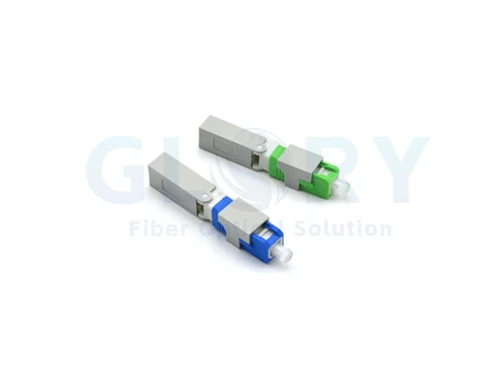
SC APC Fiber Quick Connector
The prepolished-stub, mechanical-splice type this guide is written around. The page lists a 53 mm body, insertion loss of 0.3 dB average and 0.5 dB maximum, APC return loss of 55 dB or better, a −20 to +75 °C working range, 500 mating times and a three-year warranty, for 2.0 × 3.0 mm and 2.0 × 5.0 mm drop cable or 0.9 mm round cable.
View product details →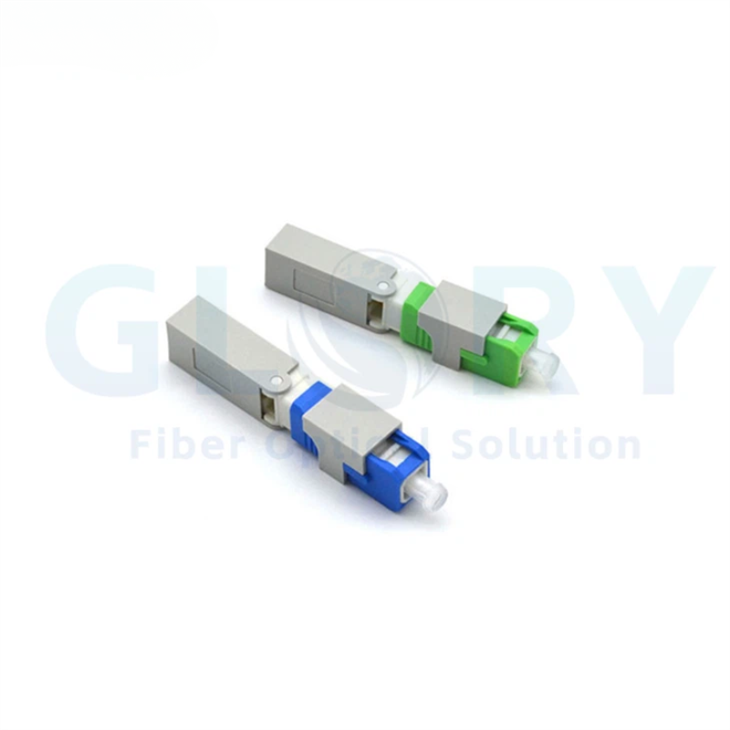
Pre-embedded fast connector, APC and UPC
The same install principle in a 55 mm pre-embedded body for 2 × 1.6 mm and 2 × 3 mm flat drop, indoor or outdoor cable, in single-mode and multimode. This page states two different APC/UPC return-loss figures for the same row, which is exactly why the trial should fix its limits against the approved datasheet rather than a page summary.
View product details →
GJXFH / GJXH flat indoor drop cable
The 2.0 × 3.0 mm flat drop construction these connectors are specified for, in one to four fibres with an LSZH jacket, −20 to +60 °C storage and working range and 80 N and 200 N short-term tensile ratings, supplied in 1 km or 2 km rolls. Agree the exact construction and the retention parts before sampling.
View product details →Product photographs are from the linked Glory Optical product pages and show the fast-connector and drop-cable families named above. They are configuration examples for the trial described here; they are not a statement that any model has been tested against, or complies with, any project's acceptance criteria or any named standard, and they are not a statement about any project's optical limits. The approved datasheet for the ordered model governs the order.
Request samples for your project cable
Send Glory your cable construction, connector interface, expected trial quantity and agreed optical requirements. Ask for samples matched to those conditions and confirmation of the sample batch.
The SC APC Fiber Quick Connector page lists free samples and a standard MOQ of 50 units. Confirm the terms and required test quantity with the team.
Request project samplesReferences
- AFL: FASTConnect product FAQ.
- FOA: prepolished/splice connectors and fiber optic installation guide.
- NIST: exact binomial confidence limits and acceptance-sampling plans.
- IEC 61300-3-4:2023, attenuation; IEC 61300-3-6:2008, return loss; IEC 61300-3-35:2022, visual inspection.
- ITU-T L.404: field-mountable single-mode optical fiber connectors.
- Fluke Networks: reflectance and optical return loss.
- Corning LAN-848-EN: silicone-based index-matching gel reliability.
Related GLORY ranges
Ranges behind the products named above: fast connectors, connectors, patch cords and adapters, fiber optic cable and OEM/ODM configuration.