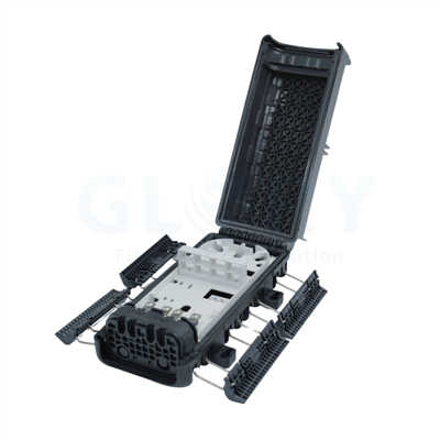
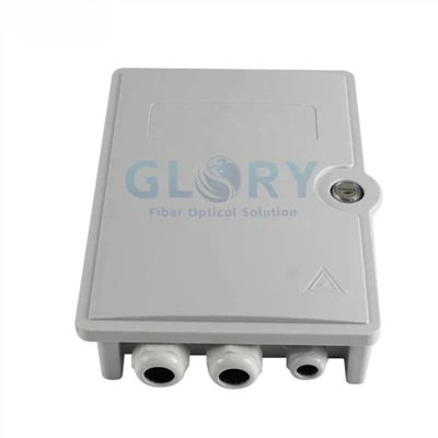
One compact platform for different last-mile architectures
The Sticklok terminal platform uses pre-terminated hardened connector assemblies that engage with numbered locking ports. It is designed to reduce field splicing at subscriber distribution points while keeping the enclosure compact enough for poles, building walls, aerial messenger routes and small underground handholes.
- MTC: cable branching and multi-fiber termination
- MTS: integrated PLC splitter configurations for PON distribution
- MTT: cascade TAP configurations for distributed splitter architectures
- STC: matched drop cable assemblies with Sticklok or SC termination
Product specifications are based on the referenced Marvel Solution with Sticklok Connector datasheet, Version A02, March 2026. Final configuration must be confirmed against the approved drawing and sample.
Designed around repeatable field connection
The locking interface is only one part of the system. The terminal also has to manage sealing, strain relief, cable routing and optical performance.
Tool-Free Port Engagement
The connector inserts into a compatible numbered port and is mechanically retained without field splicing or threaded port rotation.
Compact Modular Housing
Single- and two-layer formats provide different port densities without forcing every deployment into one enclosure size.
Retained Dust Caps
Loss-resistant protective caps remain attached to help control contamination during installation and future service work.
Outdoor Protection
UV-resistant housing, IP68 ingress protection and IK08 impact rating support exposed and underground access locations.
Multiple Network Functions
Use the same platform family for straight branching, integrated PLC splitting or distributed TAP/cascade architectures.
Cable-Specific Assemblies
Connector assemblies are matched to cable diameter and profile so tensile load, sealing and strain relief are controlled.
How the locking interface works
A locked port still requires correct model matching, clean end faces and commissioning tests.
Match the cable code
Confirm cable profile, fiber count, length and connector type before dispatching the assembly.
Inspect the interfaces
Keep dust caps in place until mating. Inspect and clean the optical interface according to the project procedure.
Insert and lock
Align the hardened connector with its assigned port, insert fully and confirm the locking mechanism is engaged.
Test and document
Verify port identification, end-to-end loss, sealing and cable strain relief before service activation.
Choose the network function first
Start with the required architecture, then select port count, layer, cable profile, splitter ratio and assembly length.
Standard cable branch configurations
| Model | Dimensions (H × W × D) | Total Ports | Layers | Insertion Loss |
|---|---|---|---|---|
| 4F Branch | 154 × 97 × 28 mm | 5 | 1 | ≤0.45 dB |
| 6F Branch, 1 Layer | 154 × 155 × 28 mm | 7 | 1 | ≤0.45 dB |
| 8F Branch, 1 Layer | 154 × 155 × 28 mm | 9 | 1 | ≤0.45 dB |
| 6F Branch, 2 Layers | 154 × 82 × 47.5 mm | 7 | 2 | ≤0.45 dB |
| 8F Branch, 2 Layers | 154 × 82 × 47.5 mm | 9 | 2 | ≤0.45 dB |
| 12F Branch | 154 × 140 × 47.5 mm | 13 | 2 | ≤0.45 dB |
| 16F Branch | 154 × 140 × 47.5 mm | 17 | 2 | ≤0.45 dB |
| 24F Branch | 154 × 198 × 47.5 mm | 25 | 2 | ≤0.45 dB |
MTC cable splitter versions
| Model | Integrated Splitters | Ports | Layers | Specified Insertion Loss |
|---|---|---|---|---|
| 4F 1×2 | 4 pcs 1:2 | 9 | 2 | ≤4.4 dB |
| 8F 1×2 | 8 pcs 1:2 | 17 | 2 | ≤4.4 dB |
| 12F 1×2 | 12 pcs 1:2 | 25 | 2 | ≤4.4 dB |
| 2F 1×4 | 2 pcs 1:4 | 9 | 2 | ≤7.6 dB |
| 4F 1×4 | 4 pcs 1:4 | 17 | 2 | ≤7.6 dB |
| 6F 1×4 | 6 pcs 1:4 | 25 | 2 | ≤7.6 dB |
| 3F 1×8 | 3 pcs 1:8 | 25 | 2 | ≤10.7 dB |
Connector configurations and cable profiles
Sticklok assemblies are available as Hardened-to-Hardened and SC/APC-to-Hardened versions. The connector body and strain-relief system are selected for a specific cable profile; similar-looking assemblies should not be treated as interchangeable.

Available cable profiles and tensile ratings
| Cable Profile | Fiber | Max IL | Short-Term Tension, 2 min | Longer-Duration Tension, 10 min | Approx. Weight, 10 m |
|---|---|---|---|---|---|
| 5.8 mm Round | G.657.A1 | 0.4 dB | 1200 N | 400 N | 330 g |
| 3.0 mm Round | G.657.A1 | 0.4 dB | 800 N | 200 N | 90 g |
| 2 × 5 mm Figure-8 | G.657.A1 | 0.4 dB | 600 N | 200 N | 210 g |
| 4 × 7 mm Flat | G.657.A1 | 0.4 dB | 600 N | 200 N | 275 g |
| 4 × 8.5 mm Flat | G.657.A1 | 0.4 dB | 600 N | 200 N | 350 g |
General terminal specifications
Mechanical and environmental test conditions
The datasheet references GR-771 and GR-3120 test methods. These references should not be treated as third-party certification unless a corresponding report is supplied.
| Test | Condition | Referenced Standard | Reference |
|---|---|---|---|
| Transportation vibration | 5–20 Hz, PSD 0.01 g²/Hz | GR-771 | R5-20 |
| Sheath retention | 10 lbf / 4.5 kg, 24 h, three temperatures | GR-771 | R5-12 |
| Cable flexing | 4.5 kg, 8 cycles, 90°, two temperatures | GR-3120 | Datasheet reference |
| Cable torsion | 10 cycles, 1 m, 20 s, 90°, two temperatures | GR-771 | R5-14 |
| Vertical drop | 75 cm, no cable, four sides, two temperatures | GR-771 | R5-15 |
| Compression | 45 kg / 25 cm², 10 min, two temperatures | GR-771 | R5-16 |
| Impact | 1 kg drop ball, 1.35 m, two temperatures | GR-771 | R5-18 |
| Water resistance | 3 m depth with cable, 7 days | GR-771 | R5-29 |
Three installation methods
Select the mounting kit together with the terminal configuration so cable entry direction and service access are resolved before shipment.

Where the platform fits
FTTP Greenfield Networks
Pre-connectorized subscriber activation points for new residential builds and phased take-rate growth.
MDU Distribution
Compact branch, splitter or cascade terminals for risers, corridors, facades and floor-level distribution.
Rural & Aerial FTTH
Small aerial or pole-mounted terminals where installation time and technician access are constrained.
Underground Handholes
Compact sealed terminals for handholes and areas where a large cabinet or vault is not practical.
Distributed Splitter ODN
MTS and MTT configurations for distributed PON splitting, cascade routes and ring-style access.
Network Retrofit
Modular additions to legacy routes when field splicing time or enclosure space must be reduced.
Information required for a correct quotation
The connector is cable-specific. Supplying complete field information at the RFQ stage prevents incompatible assemblies and unnecessary rework.
Network configuration
- Branch, splitter or TAP architecture
- Required port and fiber count
- Splitter ratio or TAP uniformity
- Single- or two-layer enclosure
- Wall, pole or aerial mounting
Cable assembly
- Round, flat, figure-8 or toneable cable
- Cable dimensions and strength-member layout
- Hardened-to-Hardened or SC/APC-to-Hardened
- Factory-terminated length and unit
- Converter/interface requirement, if any
Frequently asked questions
Q: What is a Sticklok fiber connector?
A: It is a hardened pre-connectorized interface designed to engage with a compatible terminal port without field fusion splicing. The assembly includes the optical interface, mechanical retention and cable-specific strain relief.
Q: Is this the same as a "fiber optic module lock"?
A: "Fiber optic module lock" is not a precise industry category and can also refer to transceiver or equipment security locks. For this product, "tool-free locking hardened connector" or "pre-connectorized terminal port" is more accurate.
Q: Can one connector fit every drop cable?
A: No. Cable outside diameter, shape, jacket and strength-member construction determine the correct connector and sealing components. Select the connector code for the exact cable profile.
Q: Does a locked connector mean the connection has passed?
A: No. Locking only confirms mechanical engagement. The installer should still verify end-face cleanliness, full insertion, strain relief, environmental sealing and end-to-end optical loss.
Q: Can this terminal replace all field splicing?
A: It can reduce or relocate field splicing when factory-terminated assemblies are used, but the complete network design may still require feeder splices, splitter integration or repair splicing elsewhere in the ODN.
Q: Are other hardened connector interfaces supported?
A: Converter options are listed for selected Sticklok, OptiTAP, Huawei and ZTE interface families. Exact compatibility is model-specific and should be confirmed with drawings and samples before bulk deployment.
From sample verification to project configuration
Confirm the physical interface and cable code before bulk production, then lock the approved configuration into drawings and order codes.
3-Year Service Policy
Defined return, replacement and repair support is available according to the applicable warranty terms and confirmed order documentation.
OEM/ODM Configuration
Port count, cable length, splitter structure, mounting accessories, labeling and packaging can be configured for the project.
Sample & Drawing Approval
Sample evaluation and approved drawings help confirm interface fit, sealing and cable compatibility before volume deployment

Our Quality Promise
Comprehensive 3-Year Warranty
We confidently back all our products with a 3-year warranty. Our specific service policy is: within one year for quality issues, we take full responsibility for returns; within two years, for replacements; and within three years, for repairs.
Clear & Competitive MOQ
We welcome both trial and bulk orders. Our standard Minimum Order Quantity (MOQ) is 50 units. We also offer free samples for testing to help you evaluate our quality with confidence.
Fast & Reliable Logistics
We guarantee delivery within 10 days for standard items. Our logistics advantage includes cost-effective door-to-door service to simplify shipping for you.
Our Foundation
Backed by 18 years of experience since 2008, we control quality from our own factory, accept OEM/ODM requests, and maintain ready stock for wholesale. We focus on delivering the optimal balance of price and quality directly to end customers worldwide.
Your trust is our priority. Partner with us for dependable fiber optic solutions supported by clear promises.
Hot Tags: fiber optic termination with sticklok connector, China fiber optic termination with sticklok connector manufacturers, suppliers, factory, Outdoor Fiber Optic Junction Box, Nid Box, fiber optic box outdoor, Optical Fiber Distribution Box, fiber outlet box, box fiber