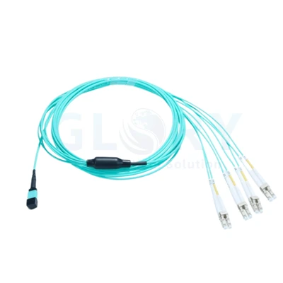
A Continuous MPO Link with Protected Connector Ends

Actual appearance: yellow jacket and MPO housings with black end caps and short rear boots. |
MPO to MPO Fiber Patch Cord (Yellow)Bring a group of optical paths to a single mating point at each end of the run. This cord uses an MPO connector on both ends, with a continuous jacketed cable between them. The pictured yellow version has a short boot behind each housing. Match the termination specification to the distribution equipment, then select a finished length that suits the cable route. |
Allow Space behind the Short Boot
Plan the route from the connector exit to the first support point. Leave room for a gradual change of direction, access to the housing and removal of the connector. A compact boot does not establish the minimum permitted bend radius.
| Installation detail | What to include in the layout |
|---|---|
| At the port face | Clearance to grip the housing and withdraw it without pulling on the jacket |
| Behind the termination | A supported cable path that avoids an immediate tight turn at the boot |
| Between cabinets or panels | Measured route length, service allowance and an identified storage location for slack |
Use the selected cable's bend and load limits when finalizing that route. Review rack patching hardware alongside the MPO connection range to check connector access before ordering.
OS2 APC Selection Profile for This Cable Format
Provisional selection profile: the values below describe a comparable twelve-fiber OS2 MPO/APC build. They require confirmation for the supplied cord. The photograph verifies the exterior design; it does not establish the concealed optical or cable specifications.
| Selection item | Appearance or reference value |
|---|---|
| Assembly name | MPO to MPO Fiber Patch Cord (Yellow) |
| Photographed construction | Yellow MPO housings and cable; black caps and short ribbed boots |
| Fiber population in the example | 12 fibers |
| Optical medium in the example | OS2 single-mode, 9/125 µm |
| End-face configuration in the example | MPO/APC at each termination |
| Alignment-pin arrangement in the example | Two female, non-pinned connector ends |
| Nominal cable diameter in the example | 3.0 mm |
| Jacket construction in the example | PVC, OFNP plenum classification |
| Length selection | Specify the finished length required by the installation |
| Reference insertion-loss criterion | <0.60 dB; agree the evaluation method for the selected assembly |
| Polarity definition | Submit the required fiber-position map and connector key orientation |
| Remaining optical acceptance fields | Confirm return-loss criterion and measurement wavelengths |
Request the agreed optical results for the completed version. The insertion-loss figure belongs to the chosen evaluation scope; complete-link acceptance must also account for the other components in the installed path.
Define the End Face, Pinning and Fiber Map Together
For the reference APC version, check that each receiving interface is intended for the corresponding angled-polish connection. Record the pin arrangement separately: each mating pair needs compatible pinned and non-pinned sides.
| Connection record | Decision needed |
|---|---|
| End A and End B interfaces | Confirm the required polish, populated positions and presence or absence of alignment pins |
| Path through the assembly | State which position at End A reaches each position at End B, with the keys identified |
| Installed port allocation | Keep those positions aligned with the approved equipment or distribution-port schedule |
The example uses female ends at both sides. Retain that choice only where the receiving connections provide the corresponding pins. Specify polarity through the approved wiring drawing rather than selecting it from the jacket or housing color.
Keep the Accepted Fiber Schedule with the Installed Cord
Label the cable so its two terminations can be located from the same record. After end-face inspection and any necessary cleaning, check the populated fibers against the approved schedule and retain the optical acceptance results under that identifier.
Protect unused ends with their caps during handling. Before a later reconnection, inspect the multi-fiber contact again with tools suited to the actual connector and pin arrangement.
Submit a Cable Schedule for Length and Termination Review
Send the End A / End B drawing, required fiber count and grade, route length, jacket requirement and quantities. Add panel access dimensions where the short-boot version must fit an existing enclosure. This gives the assembly review a defined mechanical and optical starting point.
Enquire about the Yellow MPO Version Send interface details
For related infrastructure, browse data center connectivity and discuss the overall cabling layout.
Turn the Cable Schedule into an Agreed Supply Version

Glory Optical · Ningbo production site. |
Assembly Review with the Glory Optical TeamGlory Optical has operated in Ningbo since 2008. For this MPO cord, review the proposed sample against the port drawing and cable schedule. Agree the assembly identification, inspection evidence and packing requirements so repeat orders refer to the accepted version. Meet our manufacturing operation · Review OEM project details |
Related Box and Closure Evaluation Footage
The following demonstrations concern fiber boxes and splice closures. The MPO cord requires the acceptance checks defined for its own cable assembly.
Water Spray Evaluation |
Seal Performance Evaluation |
Water Resistance Evaluation |
Hot Tags: os2 apc mpo to mpo fiber patch cord, China os2 apc mpo to mpo fiber patch cord manufacturers, suppliers, factory, data center cabling, data center fiber cabling, Mpo 12 Fiber Cable, mtp mpo, Mtp Mpo Fiber Breakout Cable, Mtp To Lc Breakout Cable