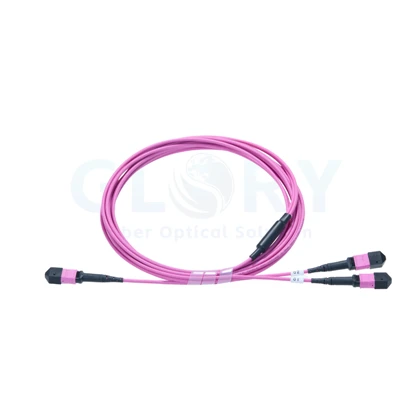
An Aqua MPO Cord with Extended Ribbed Rear Boots

Pictured version: aqua cable and connector bodies, black caps and long ribbed rear boots. |
MPO to MPO Fiber Patch Cord (Aqua, Ribbed Boot)Terminate a multi-fiber patching run in one MPO plug at either end. The cord shown here combines aqua housings with elongated, ribbed black boots at the cable entries. Use this version where the MPO port arrangement and the available space behind the connection have been defined. Its direct end-to-end format keeps the optical paths together along the jacketed run. |
Reserve a Clear Exit Path for the Extended Boot
Check the distance from the panel face to the first cable guide. The long rear section occupies space before the cable enters the routing channel, so include the complete connector-and-boot envelope in the panel layout.
| Visible feature | Practical handling point |
|---|---|
| Aqua push-pull housing | Keep the housing accessible when positioning or releasing the connector |
| Elongated ribbed boot | Leave the rear transition clear of a sharp turn or pressure from a closed panel door |
| Black removable cap | Protect the unmated end during storage; inspect the contact before connection |
Choose the actual cable bend radius from the approved assembly specification. The visible ribs do not define a numerical bend limit or a tensile rating. Check this physical version with the intended fiber patch panel before a cabinet layout is fixed.
Reference Data for a Twelve-Fiber OM4 Build
Selection reference, subject to confirmation: this table uses a comparable published OM4 MPO cord profile. It is a starting point for the requested assembly. The photograph confirms the exterior version; concealed fiber, connector and jacket specifications still require verification.
| Parameter | Pictured format or reference configuration |
|---|---|
| Product | MPO to MPO Fiber Patch Cord (Aqua, Ribbed Boot) |
| Visible termination format | One MPO housing at each cable end; aqua finish with long black ribbed boots |
| Reference fiber specification | 12 fibers; OM4 multimode, 50/125 µm |
| Reference connector format | MPO to MPO |
| Reference wiring option | Type B; approve the fiber map and key orientation for the actual link |
| Reference jacket outside diameter | 3 mm |
| Reference installation classification | Plenum |
| Reference insertion loss | ≤0.60 dB |
| Reference return loss | ≥20 dB |
| Reference operating range | -20°C to +70°C |
| Finished cable length | Set from the cable schedule; photographed length is unverified |
| End-face and alignment details | Confirm polish and pinned / non-pinned arrangement at both ends |
Treat the loss values as criteria for the agreed test method and assembly scope. Verify the complete installed channel against the selected equipment requirements when other connectors and cable sections are present.
Record Each Optical Path across the Two MPO Ends
A multi-fiber cord carries several optical paths through one physical connection. Give both ends an identifier and record the arrival position of every populated fiber. That record allows the cable to be checked independently of its installed port labels.
| Record to retain | Purpose during installation |
|---|---|
| End-to-end position schedule | Shows the destination position of each populated fiber |
| Connector keys and pin arrangement | Defines how each termination fits its mating interface |
| Per-fiber acceptance results | Associates the measured optical paths with the approved cord version |
Type B is the reference wiring option in the table. Use it only where the overall connection plan requires that map. Confirm the required gender and polish with each receiving interface; every mating pair must have compatible pinned and non-pinned sides.
Use the Housing for Release and Inspect before Reconnection
Make room to operate the push-pull housing without tugging the jacket. Support the cable while removing a connector, and keep the freed end away from exposed surfaces. Retain a cap for storage between uses.
Before reconnection, examine the multi-fiber face with a suitable inspection system. Clean if needed and inspect again. Select tools for the actual pinning and connector format so the contact can be prepared without relying on the appearance of the protective cap.
Define the Requested Cord in a Single Project Line
Include the two port descriptions, fiber population, required grade, wiring map and finished length. Add the ribbed-boot version, jacket class, labels and quantity. Where access is restricted, provide the panel depth and cable-guide position for a fit review.
Request an Aqua MPO Cord Review Discuss connector fit
Find related MPO assemblies within the data center product range, or review the cabling arrangement for the project.
Glory Optical Assembly and Project Support

Manufacturing location in Ningbo · Glory Optical. |
Agree a Sample against the Project Cable ListBased in Ningbo and established in 2008, Glory Optical works on passive fiber connectivity requirements. Bring the cable list and interface drawings to the sample review. The accepted version should identify the connector hardware, cable construction and records required with the order. |
Enclosure Demonstrations from the Company Video Library
These demonstrations feature fiber boxes and splice closures. Optical and mechanical acceptance for this MPO cord follows its agreed cable specification.
Water Spray Evaluation |
Seal Performance Evaluation |
Water Resistance Evaluation |
Hot Tags: om4 mpo to mpo fiber patch cord, China om4 mpo to mpo fiber patch cord manufacturers, suppliers, factory, data center cabling, data center fiber cabling, mtp mpo, Mtp Mpo Fiber, Mtp Mpo Fiber Breakout Cable, Mtp To Lc Breakout Cable