The Quick Answer
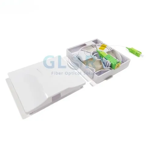
A fiber optic pigtail is a short fiber, usually 0.5–2 m, with one factory-polished connector and one bare fiber end that is fusion spliced into a trunk or drop cable. Choose a pigtail over a patch cord whenever the termination is permanent - inside an ODF, splice closure, fiber distribution box or terminal box - because a one-time fusion splice gives lower, more stable loss than a re-pluggable cord. The most common specifications are SC/APC for FTTH/PON, LC/UPC for data centers and high-density ODFs, 0.9 mm tight-buffered cable for splice trays, and G.657.A2 bend-insensitive fiber for compact FTTH boxes.
| If you need to… | Best choice | Common starting spec |
|---|---|---|
| Terminate a trunk/drop fiber permanently in an ODF, closure or box | Pigtail | SC/APC or LC/UPC, 0.9 mm, G.657.A2 / OS2 |
| Connect two devices or panels you will re-plug over time | Patch cord | LC/UPC duplex, 2.0 mm, 1–3 m |
| Terminate an FTTH drop with no fusion splicer on site | Fast connector | SC/APC field-installable connector |
Use this page to move from "what is a pigtail" to a decision you can specify, splice, test and buy. Planning values such as connector-pair loss, splice loss and acceptance thresholds must still be confirmed against the product datasheet, the system loss budget and the operator's acceptance rules. Sending a quote? Include connector type, polish, fiber type, length and quantity, plus your BOM, so the response is project-specific the first time.
Pigtail vs Patch Cord vs Fast Connector
On site, the real question is rarely "what is a pigtail" - it is "which termination solves this job with the lowest long-term risk." All three options are valid, and choosing the wrong one usually shows up months later as rework. The structural difference decides the use case.
- A pigtail has one factory connector and one bare fiber end. It is fusion spliced once, then disappears inside an enclosure and is never unplugged.
- A patch cord has connectors on both ends and a jacketed cable in between. It sits in open racks for daily plug-and-play.
- A fast connector is a field-installable connector crimped onto a stripped fiber on site, with no fusion splicer required. It solves quick repairs and no-splicer drop work where time matters more than the last fraction of a dB.

| Use case | Best choice | Why |
|---|---|---|
| ODF / trunk termination | Pigtail | Permanent fusion splice, lowest and most stable loss |
| FTTH wall outlet / terminal box | SC/APC pigtail or fast connector | Depends on whether a splicer is available on site |
| Data center rack-to-rack connection | Patch cord | Frequent moves, adds and changes; both ends are devices |
| Emergency field repair | Fast connector | Fast restoration when no splicer is on the van |
| Splice closure restoration | Pigtail | Lower long-term loss over a sealed, undisturbed joint |
Cutting a patch cord in half to "make two pigtails" looks like a saving but rarely is: you lose the factory test record on the cut end, and a 2.0–3.0 mm jacket is far harder to dress into a 30 mm splice-tray radius than a 0.9 mm pigtail. Keep it for genuine emergencies and use purpose-built pigtails for planned work.
How to Choose the Right Fiber Optic Pigtail
A pigtail specification is a short list of decisions: connector and polish, fiber type, cable construction and diameter, and length. Get those four right and a supplier cannot misread the order. The subsections below turn the classification into a selection checklist.
Connector Type: SC/APC vs LC/UPC
The connector and its polish determine where the pigtail belongs and how much light reflects at the joint. The polish - PC, UPC or APC - sets return loss; the connector body sets density and the equipment it mates to. For a deeper treatment of formats and polish geometry, see the complete fiber connector guide, and for available formats the
fiber optic connector range.
- SC/APC - the FTTH and PON standard. Used on GPON, XGS-PON, fiber distribution boxes, wall outlets and ONT-side terminations. The 8° angle steers back-reflection into the cladding, protecting PON burst receivers and RF-over-glass overlays.
- LC/UPC - the density standard. Used in high-density ODFs, data centers, transceivers and patch panels, where the 1.25 mm LC ferrule fits the most ports per rack unit.
- SC/UPC - still used in some legacy or non-PON systems and in test and maintenance work.
- LC/APC - used where both high density and low reflection are needed, such as some carrier and special-project links.
- Never mate APC with UPC. The angle mismatch inflates insertion loss and can damage both end faces. APC uses a green boot, UPC a blue boot - color is your first check.
| Connector | Polish | Common use | Boot color | Typical buyer |
|---|---|---|---|---|
| SC/APC | 8° angled | FTTH / GPON / XGS-PON | Green | ISP / ODN |
| LC/UPC | Ultra physical contact | Data center / ODF | Blue | Data center / enterprise |
| SC/UPC | UPC | Legacy telecom / test | Blue | Maintenance / replacement |
| LC/APC | APC | High-density, low-reflection links | Green | Carrier / special project |
Fiber Type
Keep fiber selection practical and match it to the route, not to a full singlemode-versus-multimode study:
- G.652.D - standard singlemode for backbone and outdoor trunk routes with generous bend radii. Defined in ITU-T G.652.
- G.657.A2 - bend-insensitive singlemode for FTTH terminal boxes and tight routing; fully splice-compatible with G.652.D plant. Defined in ITU-T G.657.
- OM3 / OM4 - multimode for data center pigtails on VCSEL-based links.
For the full comparison of mode types and reach, see the related guide on singlemode vs multimode fiber rather than expanding it here.
Cable Diameter and Structure
The cable section between connector and bare tail comes in several forms, each with a clear home:
- 0.9 mm tight-buffered - the default for splice trays; flexible and easy to dress.
- 2.0 mm / 3.0 mm jacketed - more mechanical protection for high-traffic panels and customer-side boxes.
- 12-fiber bunch pigtail - many tails under one jacket for ODF and high-count termination; lets one technician finish a cabinet in a single shift.
- Ribbon pigtail - fibers side-by-side for mass-fusion splicing in high-volume central offices.
- Armored / waterproof pigtail - for outdoor, FTTA and industrial environments where rodents, impact or moisture are a risk.
Length
Length should match the enclosure depth and slack routing, not be guessed:
- 0.5 m - compact wall outlet or small terminal box.
- 1.0 m - small splice tray.
- 1.5 m - the common ODF, closure and FDB default.
2.0 m and up - deeper cabinets or custom routing; specify exactly to avoid stretching or coiling excess.

Fusion Splice Workflow for Fiber Optic Pigtails
Fusion splicing a pigtail to a trunk or drop fiber is the most common skill in fiber field work - and the one most often done badly. The workflow below is grouped into preparation, splicing and finishing. Tooling is described by category rather than by brand, because any quality core-alignment splicer, precision cleaver, stripper and inspection scope will do the job.

Use a simple pass / rework checklist at the splice point so problems are caught before the tray is closed:
| Checkpoint | Target | Action if failed |
|---|---|---|
| Cleave angle | Clean, flat end face | Re-cleave |
| Estimated splice loss | Project threshold (often ≤0.10 dB) | Re-splice |
| Tray routing | No tight bend / no fiber stress | Re-route within bend radius |
| Labeling | Port and fiber ID match drawing | Correct before closure |
| End-face inspection | Clean before mating | Clean and re-inspect |
Insertion Loss Testing and Acceptance
Testing is the final quality gate before a pigtail-terminated link is handed over. The single most preventable cause of high connector loss is a contaminated end face, so inspection comes first, then loss measurement, then OTDR verification, with the VFL as a quick continuity aid only.
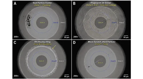
End-Face Inspection
Inspect, clean, inspect - every time, on both the pigtail connector and the adapter or port it mates to. Use a fiber inspection scope and apply the pass/fail criteria of IEC 61300-3-35, the international standard for connector end-face acceptance. Dust, oil and scratches in the core zone scatter or block light and drive insertion loss up, so never connect a dirty APC or UPC ferrule. For multi-fiber connectors, where one contaminated fiber can degrade the whole array, follow the dedicated MPO/MTP connector cleaning and care procedure with an MPO probe tip and the right cleaning tools.
Optical Power Meter / OLTS Insertion Loss Test
The power meter gives a direct, absolute measurement of the loss across the link. The workflow is short:
- Set a reference with a light source and a known reference cord.
- Insert the pigtail-terminated link under test.
- Measure the received power.
- Calculate insertion loss.
- Compare against the project loss budget.
IL = Reference Power − Measured Power (in dB). A result that exceeds the budget by more than a small margin warrants an OTDR investigation to find the contributing event.
Acceptance examples, expressed as planning ranges rather than universal limits:
- Connector pair - project-defined; commonly planned around 0.20–0.30 dB.
- Fusion splice - commonly targeted around 0.05–0.10 dB.
- Final link - must stay within the designed loss budget for the system class.
There is no single insertion-loss value that is correct for every project. PON, enterprise and data center links each set their own budgets, and the standard being applied matters. Always take the acceptance number from the system design and the operator's rules, and treat the figures above as starting points for the budget conversation.
OTDR Verification
An OTDR maps every event along the link - connector reflections as spikes, splices as small step-downs. For pigtail terminations, test per IEC 61280-4-1:
- Use a launch cable so the first connector reflection sits outside the OTDR dead zone and the near-end splice can be measured.
- Verify the splice event appears as a small loss step with no large reflection.
- Check the reflection at the connector - APC links should show very low reflectance.
- Save the OTDR trace as part of the as-built documentation.
Bidirectional testing (averaging A→B and B→A) is preferred for acceptance, because event loss is directional.

VFL Continuity Check
A visual fault locator injects visible red light and is useful for two quick jobs: confirming continuity (light visible at the far end) and finding a macrobend (light leaking through the jacket at a tight bend). It is fast, but it is not a substitute for IL or OTDR acceptance testing and should never be the only test on a link handed to a carrier or submitted as as-built.
Packaging, Labeling and Bulk Procurement
For project buyers and OEM sourcing teams, the specification and the documentation matter as much as the connector. A complete RFQ produces a correct order the first time; a vague one produces revisions, mismatched polish and missing test data.
What to Specify in an RFQ
Provide all of the following so the supplier cannot misinterpret the order:
- Connector type: SC, LC, FC, ST, MPO
- Polish: APC or UPC
- Fiber type: G.652.D, G.657.A2, OM3, OM4
- Cable diameter: 0.9 mm, 2.0 mm, 3.0 mm
- Length: 0.5 m, 1.0 m, 1.5 m, or custom
- Configuration: simplex / duplex / 12-fiber bunch / ribbon
- Jacket color and boot color
- IL / RL requirement
- Packaging method
- Quantity and delivery schedule
- Required certificates or batch test reports
"Please quote: SC/APC simplex pigtail, G.657.A2, 0.9 mm, 1.5 m, green boot, yellow jacket, IL ≤0.20 dB, RL ≥60 dB, individually packed, label by batch number, quantity 5,000 pcs. Provide per-batch IL/RL test data and confirm lead time and batch split."
Packaging Options
Packaging protects the factory loss figure all the way to the splice tray. Specify it deliberately:
- Individual dust cap and polybag per pigtail
- Bulk bags in standard counts (e.g. 12 / 50 / 100 pcs)
- Carton labeling by connector type, length, fiber type and batch
- Color-coded labels for APC vs UPC
- Coiled without tight bending
- Desiccant for long storage
- OEM or private-label packaging where required
Batch Test Report Requirements
For project acceptance and traceability, ask for documented test data, not a generic carton label:
- IL test data
- RL test data
- End-face inspection result
- Batch number
- Date of production
- Operator or QC station ID
- Sampling or 100% test method
CSV data export for large orders

MOQ and Lead Time
Keep MOQ and lead-time expectations realistic and confirm them in writing before the purchase order:
- Standard simplex pigtails usually allow a low MOQ.
- Bunch pigtails are typically ordered by the set, with MOQ per set.
- Custom length, custom color or OEM packaging carry a higher MOQ and longer lead time.
- For large orders, confirm lead time, batch split and QC documentation before issuing the PO.
Do not compare on unit price alone. A narrow IL distribution, unit-level traceability, protective packaging and a responsive supplier are worth more over a project's life than a few cents per piece. The cheapest pigtail becomes the most expensive one the first time a tail-end subscriber needs a truck roll.
Common Ordering Mistakes
Most expensive pigtail problems are specification or handling errors, not bad product. Design these out before the order is placed:
- Ordering UPC instead of APC for GPON / FTTH.
- Choosing a 3.0 mm jacket when 0.9 mm is needed for the splice tray.
- Buying pigtails with no test reports.
- Mixing G.652.D and G.657 fiber without checking bend and loss requirements.
- Cutting patch cords to make pigtails for permanent installation.
- Ignoring packaging and dust-cap quality.
- Not confirming the color code for 12-fiber bunch pigtails.
- Using a VFL as the only acceptance test.
- Not requesting batch traceability for large projects.
- Ordering a length too short for deep closures or cabinets.
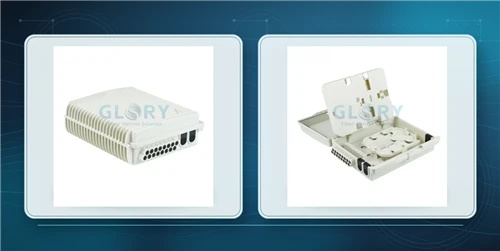
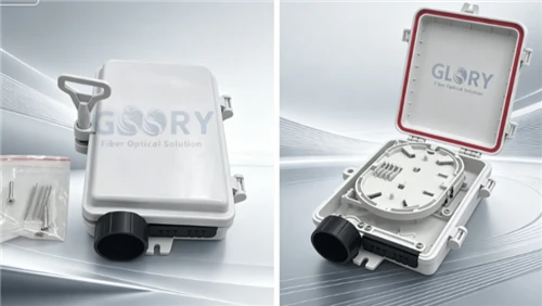
Application-Based Recommendations
Most B2B pigtail procurement falls into a handful of scenarios. The mapping below is a starting point - confirm exact fiber count, polish and length against your design.
| Application | Recommended pigtail | Why |
|---|---|---|
| FTTH terminal box | SC/APC, G.657.A2, 0.9 mm | Bend-insensitive and PON-ready |
| ODF trunk termination | LC/UPC or SC/APC 12-fiber bunch | Faster high-count splicing |
| Data center patch panel | LC/UPC OM4 or OS2 bunch pigtail | High-density termination |
| Outdoor splice closure | SC/APC outdoor-rated pigtail | Better environmental protection |
| OEM kit assembly | Custom length, label and package | Easier project deployment |
SC/APC Single-Mode Pigtail
0.9 mm tight-buffered, G.657.A2 bend-insensitive, 0.5–2.0 m. The FTTH workhorse for terminal boxes, wall outlets and ONT-side terminations. Confirm IL/RL targets against your budget.
View SC/APC pigtailsLC/UPC Bunch Pigtail
12-fiber bunch, color-coded, 0.9 mm, OS2 or OM4. High-density ODF and patch-panel termination that lets one technician finish a cabinet in a shift.
View LC bunch pigtailsSC/APC Fast Connector
Field-installable, no fusion splicer required. The right tool for emergency drop repairs and first-install CPE terminations pending a scheduled fusion splice.
View fast connectorsFiber Patch Cords
SC/APC, LC/UPC and LC/APC, simplex and duplex, for equipment-to-panel and panel-to-panel connections where you re-plug over time.
View patch cordsFAQ
Q: What is a fiber optic pigtail?
A: A fiber optic pigtail is a short length of optical fiber, usually 0.5 m to 2 m, with a factory-polished connector on one end and a bare fiber on the other. The bare end is fusion spliced to a fiber in a trunk or drop cable, and the connector end is mounted in an adapter on a panel or box. Because the connector is polished and tested in a factory, a pigtail termination is repeatable and low loss compared with hand-polished field termination.
Q: What is the difference between a pigtail and a patch cord?
A: A pigtail has one connector and one bare fiber end, so it is spliced once inside an enclosure and then left undisturbed. A patch cord has connectors on both ends and a fully jacketed cable, so it plugs between two devices or panels and can be unplugged and reconnected repeatedly. Use pigtails for permanent termination in ODFs, closures and terminal boxes, and patch cords for equipment-to-panel or panel-to-panel links.
Q: Can I cut a patch cord to make a pigtail?
A: You can, but it is not recommended for permanent installations. Cutting a patch cord loses the factory test data on the cut end, and a 2.0 mm or 3.0 mm jacketed cable is harder to dress into a splice tray than a 0.9 mm pigtail. For a one-off emergency repair it can be acceptable; for planned ODF, closure or FTTH work, use purpose-built pigtails so the loss budget and traceability stay intact.
Q: When should I use SC/APC pigtails?
A: Use SC/APC pigtails for GPON, XGS-PON and other PON-based FTTH, in fiber distribution boxes, wall outlets and ONT-side terminations. The 8° angled polish keeps return loss high, which protects the burst-mode upstream receivers used in PON and any RF-over-glass overlay. APC connectors use a green boot and must never be mated to a UPC (blue boot) connector.
Q: When should I use LC/UPC pigtails?
A: Use LC/UPC pigtails in high-density ODFs, data centers, patch panels and transceiver breakouts, where the small 1.25 mm LC ferrule fits the most ports per rack unit. UPC suits digital links that do not carry analog RF video. Confirm whether the equipment expects UPC or APC before ordering, because polish type cannot be mixed at a mated pair.
Q: How do you fusion splice a pigtail?
A: Confirm the pigtail spec and polarity, inspect the connector end face, then slide a heat-shrink sleeve onto the fiber before stripping. Strip the coating, clean with isopropyl alcohol and a lint-free wipe, and cleave for a flat end face. Load the trunk fiber and pigtail into a fusion splicer, run the arc and read the estimated splice loss, then shrink the protection sleeve. Route the fiber in the splice tray within its minimum bend radius, label the port, and verify with a power meter and OTDR.
Q: How do you test insertion loss after splicing?
A: Set a reference with a light source and a known reference cord, then insert the pigtail-terminated link and measure the received power. Insertion loss is the reference power minus the measured power. Compare the result against the project loss budget. Inspect and clean every end face before mating, and use an OTDR with a launch cable to verify the splice event and connector reflection and to save a trace for as-built documentation.
Q: What is a good insertion loss value for a pigtail?
A: There is no single universal number, because acceptance depends on the project loss budget and the standard being applied. As a planning guide, a fusion splice is commonly targeted around 0.05 to 0.10 dB and a mated connector pair is often planned around 0.20 to 0.30 dB, with the final link required to stay inside its designed budget. Always set the acceptance value from the project design and the operator's rules, not from a generic figure.
Q: What information should I provide when buying pigtails in bulk?
A: Provide connector type (SC, LC, FC, ST, MPO), polish (APC or UPC), fiber type (G.652.D, G.657.A2, OM3, OM4), cable diameter (0.9, 2.0 or 3.0 mm), length, and whether you need simplex, duplex, bunch or ribbon. Add jacket and boot color, IL/RL requirements, packaging method, quantity, delivery schedule, and any certificates or batch test reports needed. The more complete the RFQ, the fewer revisions before the order is correct.
Q: Can pigtails be customized with OEM packaging?
A: Yes. Pigtails can be supplied with custom length, jacket and boot color, private-label or co-branded packaging, color-coded labels for APC and UPC, and per-batch test certificates. Custom configurations usually carry a higher minimum order quantity and a longer lead time than standard catalog items, so confirm MOQ, batch split and documentation before placing the purchase order.
Standards & References
The references below help engineers verify the values used in pigtail selection, splicing, testing and acceptance. Always check the current edition and the operator's local acceptance rules before final approval.
| Reference | Why it matters for pigtails |
|---|---|
| ITU-T G.652 | Standard single-mode fiber used in backbone and trunk pigtails. |
| ITU-T G.657 | Bend-insensitive single-mode fiber for FTTH terminal-box and tight-routing pigtails. |
| IEC 61754 | Fiber optic connector interface standards (SC, LC, MPO and others). |
| IEC 61300-3-35 | Connector end-face inspection zones and pass/fail criteria; use the current edition. |
| IEC 61280-4-1 | Installed cable plant attenuation and OTDR measurement procedures. |
| IEC 61753-1 | Performance standard and grades for connector insertion loss and return loss. |
| Telcordia GR-326-CORE | Single-mode connector reliability and durability baseline. |
| TIA-598 / TIA-568 | Fiber color coding and connector polarity methods for bunch and MPO pigtails. |
About Glory Optical: Ningbo Glory Optical Communication Co., Ltd. supplies FTTH / FTTx passive optical components including fiber optic pigtails, patch cords, connectors, adapters, termination boxes, splice closures, PLC splitters and ODN accessories, with OEM and ODM support. Product values in this article should be confirmed against the latest datasheet or project-specific RFQ.
Document note: This guide is for technical planning and procurement support. Insertion-loss, return-loss and acceptance figures are planning ranges, not universal limits - they do not replace local codes, operator standards, certified design review or product-specific installation instructions.