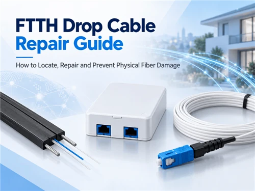
An FTTH drop cable can often be repaired after localized physical damage, but replacement is usually the better choice when the run is short, damage extends beyond one point, or the remaining cable cannot be supported and sealed correctly.
ITU-T L.105 (11/2025) defines optical drop cables as the customer connection to an optical access network and emphasizes that cable characteristics should match the conditions of the actual installation environment. Its August 2026 Corrigendum 1 adds material covering aging, longitudinal water penetration, moisture permeation, and rodent and insect damage. See ITU-T L.105.
Before Repair: Confirm the Fault Is in the Drop Cable
Start by separating an active-equipment or connector problem from a passive drop cable fault.
In a PON network, useful first checks can include the ONT/ONU alarm state, received optical power, connector condition, and available OLT/ONU performance information. ITU-T specifications for PON systems include monitoring of optical parameters such as transmitted and received optical power, which can support fault isolation before the cable is cut or replaced.
| Check | What it helps determine |
|---|---|
| ONT/ONU status and alarms | Whether the subscriber terminal has lost optical service |
| Optical power | Whether received power is abnormal relative to the operator's limits |
| Connector inspection and cleaning | Whether contamination or connector damage is contributing to loss |
| Drop terminal/reference-point measurement | Whether the abnormal loss is on the subscriber side or farther upstream |
| Route inspection | Whether there is evidence of physical cable damage |
| VFL or OTDR | Where the suspected fiber fault is located |
A pass-through PON power meter can also help separate upstream and downstream portions of an active PON while allowing the OLT and ONT to remain in communication. See EXFO's FTTx/PON testing reference.
Be careful when testing a live PON with an OTDR
A standard construction OTDR should not automatically be connected to an active PON.
For in-service troubleshooting, testing equipment and wavelengths must be compatible with the live network. Filtered live-PON OTDR ports commonly use out-of-band wavelengths such as 1625 or 1650 nm so that the test signal can be separated from service wavelengths. The exact method depends on the PON generation, network design and operator procedure. See EXFO's in-service FTTH troubleshooting note.
Fiber safety comes before inspection
Optical power in a communications fiber may be invisible.
IEC 60825-2:2021 provides safety requirements and guidance for operation and maintenance of optical fiber communication systems. FOA likewise advises technicians not to judge whether a fiber is active by looking into the end of it; verify optical power first or use appropriate filtered inspection equipment. See IEC 60825-2:2021.
Locate the Physical Damage
Use the simplest method that can answer the fault-location question reliably.
Start with the cable route
Inspect accessible sections for:
- cuts from gardening or construction tools;
- crushed or flattened jacket;
- sharp kinks;
- damaged building-entry points;
- cable pulled out of a clamp;
- unsupported aerial sections;
- disturbed duct or handhole routes;
- recent drilling, excavation or cable pulling near the drop.
Do not assume that a visibly damaged jacket marks the entire affected section.
Practical implication: internal fiber damage can extend beyond an obvious external mark.
Use a VFL for appropriate short and accessible paths
A visual fault locator can help with continuity, fiber identification and locating certain breaks or severe bends where visible red light escapes from the fiber.
FOA specifically identifies VFLs as useful for finding faults near a cable end, including locations where OTDR dead zones can make interpretation difficult. See the FOA Visual Fault Locator guide.
There is no useful universal rule such as "always use a VFL below X meters and an OTDR above X meters." The decision depends on:
- route accessibility;
- cable construction;
- distance to the suspected event;
- connector configuration;
- whether the network is active;
- the resolution of the available OTDR.
An opaque outdoor jacket may also prevent escaped VFL light from being visible. A lack of visible red light through the jacket does not prove that the fiber is healthy.
Glory's current fiber optic tool range includes a 650 nm VFL, optical power meter and flat-drop preparation tools for FTTH field work. They are relevant tools in the troubleshooting chain, but instrument selection should follow the fault and network condition rather than a fixed kit.
Use an OTDR when the fault location is uncertain
An OTDR becomes more useful when:
- the drop is buried or concealed;
- several route sections are inaccessible;
- visual inspection finds no clear damage;
- distance to a loss or reflective event is needed;
- the repair needs to be compared with a previous trace.
Remember that an OTDR reports optical distance along the fiber, not an exact excavation coordinate. Stored slack, route geometry and cable configuration must be considered when translating trace distance into a physical location.
Where baseline traces are available, compare the fault trace with the original installation record instead of interpreting the new trace in isolation.
Repair or Replace the FTTH Drop Cable?
The key question is whether the resulting repair will be simpler and more reliable than replacing the affected drop.
Four restoration paths cover most field situations.
| Restoration path | Best candidate | Main limitation |
|---|---|---|
| Complete drop replacement | Short or accessible run; widespread damage; incorrect existing cable | Requires rerouting/pulling the full subscriber run |
| Mid-span fusion splice | One localized break on a difficult or long route | Requires sufficient healthy cable and a suitable protected splice point |
| Re-terminate the cable end | Damage is close to the subscriber or terminal end | Does not solve damage farther along the cable |
| Replace with pre-terminated drop | Known route and connector system; plug-and-play architecture | Length, connector interface and pulling clearance must be correct |
1. Replace the complete drop
Full replacement is normally the cleaner option when:
- the subscriber run is short and easy to access;
- several sections have been crushed or damaged;
- cable strength members have been compromised over a larger area;
- the existing cable is unsuitable for the environment;
- another splice would create a poor mechanical location;
- insufficient slack remains for a proper repair.
The replacement cable should match the route rather than simply duplicate the damaged cable.
Glory's FTTH cable range includes indoor, outdoor, flat and self-supporting structures using G.657-series fibers for subscriber access applications.
2. Make a localized fusion-splice repair
A mid-span splice becomes a stronger candidate when:
- damage is confined to one identifiable section;
- rerunning the complete drop would be disruptive;
- sufficient healthy cable remains on both sides;
- cable strength members can be properly retained;
- an appropriate enclosure can protect the restored section.
Localized repair is an established access-network practice. Corning, for example, offers dedicated fiber drop repair closures specifically for extension or repair of damaged drop cables. One current two-fiber model supports two splices, 3.8–6.2 mm cable entries, gel sealing and an IP68 design. See the Corning drop repair closure example.
Those specifications illustrate why the enclosure must be matched to the actual cable. "Small splice closure" is not a sufficient procurement description.
3. Re-terminate near the subscriber end
If the cable damage is confined to the final termination area, cutting the cable back to healthy material and re-terminating it may avoid an unnecessary mid-span joint.
Depending on the approved network design, this may involve:
- fusion splicing to a pigtail;
- installing an approved field connector;
- re-terminating inside a fiber termination box.
A field connector designed for subscriber termination should not automatically be used as an exposed outdoor mid-span repair.
For example, Glory's GL-FTB-4F termination box provides a protected endpoint for fiber termination and storage. Use it where the network design calls for a termination point; it is not a substitute for a dedicated inline repair closure in the middle of an exposed route.
4. Replace a pre-terminated drop assembly
In pre-connectorized FTTH architectures, replacing the complete drop assembly can sometimes eliminate field splicing.
Before using this approach, verify:
- actual route length;
- hardened connector interface;
- terminal compatibility;
- pulling-eye or connector-envelope clearance;
- bend points along the route;
- whether one or both ends must be connectorized.
Glory lists pre-terminated fiber optic cable assemblies for access-network applications, including configurable cable and connector arrangements.
Recommended Glory Products for Different Repair Paths
The repair method determines which component belongs in the field kit. The products below are matched to three different restoration scenarios rather than presented as interchangeable substitutes.

GJXFH / GJXH Indoor Drop Fiber Cable
Use this route when the damaged subscriber run is better replaced than spliced. The published Glory model is a flat last-mile drop cable for indoor access and direct subscriber connection.
Best for: complete replacement of a short or accessible indoor FTTH drop.

GL-FTB-4F 2-Port Fiber Termination Box
A compact subscriber-side termination point for splicing, fiber storage and adapter termination. It fits the repair path where damage is near the premises or endpoint and the cable can be cut back to healthy material.
Best for: endpoint re-termination rather than an exposed mid-span repair.

Huawei Mini SC Pre-Terminated Fiber Optic Cable
A factory-terminated drop assembly for routes where length and connector interfaces are already known. It can replace a damaged drop without adding a new field splice when the installed terminal system is compatible.
Best for: planned plug-and-play replacement in a compatible pre-connectorized FTTH architecture.
How to Repair a Localized Drop Cable Break
Once localized repair has been selected, the objective is to restore both the optical path and the mechanical cable system.
Step 1: Define the affected section
Confirm that the identified cable belongs to the correct subscriber and inspect beyond the visible damage.
Look for:
- elongated or distorted jacket;
- damaged strength members;
- kinked sections;
- crush marks;
- evidence that the cable was pulled after it broke.
Remove enough damaged cable that both retained ends are structurally sound.
Step 2: Create enough working length
A fusion splice cannot be installed reliably if the remaining cable is under tension.
Provide enough cable for:
- preparation;
- splicing;
- splice protection;
- routing inside the enclosure;
- future re-entry where required.
If adequate working length cannot be obtained without overstressing the existing drop, replacement may be the better option.
Step 3: Prepare the cable according to its construction
Flat FTTH drop cable, round drop cable and reinforced outdoor cable do not use the same preparation method.
The technician should identify:
- jacket structure;
- strength members;
- buffer/fiber location;
- messenger or support element, if present;
- the correct stripping tool.
Do not allow pulling load from the cable or strength members to transfer directly to the bare fiber or completed splice.
Step 4: Prepare and splice the fiber
For a fusion-splice repair:
- strip the fiber coating using the correct tool;
- clean the bare fiber;
- cleave both fiber ends;
- perform the fusion splice;
- inspect the splicer result according to the operator's procedure;
- install the specified splice protector;
- place the protected splice in the tray or holder.
A generic maximum splice-loss number should not be applied to every FTTH repair. The acceptance limit should come from the network owner, project specification or applicable test plan.
Step 5: Restore cable strength and strain relief
The splice itself should not carry cable tension. Secure the cable and its strength members using the retention system designed for the enclosure. Check that normal cable movement cannot pull directly on the protected fiber.
Step 6: Route the fiber and slack
Store the remaining fiber without:
- sharp turns;
- pinching under tray covers;
- crossing sealing surfaces;
- excessive tension;
- interference with other splices.
The exact bend limit should follow the fiber, cable and enclosure requirements rather than a generic value copied from another product.
Step 7: Close and seal the repair
Only after the splice, cable retention and routing have been checked should the enclosure be sealed.
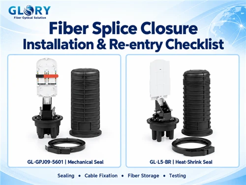
The detailed procedures for cable-entry preparation, sealing, tray routing and future re-entry belong to the closure installation process rather than this drop-repair guide. See Glory's Fiber Splice Closure Installation & Re-entry Checklist for those steps.
Select a Closure That Fits the Repair
The enclosure used for a permanent outdoor repair must protect more than the splice sleeve. It also has to manage the cable mechanically and environmentally.
| Requirement | Repair decision |
|---|---|
| Cable diameter | Does each entry seal support the actual drop cable OD? |
| Number of fibers | Are enough splice positions available without unnecessary enclosure size? |
| Strength-member retention | Can the cable be anchored independently from the fiber? |
| Fiber routing | Is there enough controlled space for the splice and slack? |
| Environmental exposure | Is the sealing design appropriate for the location? |
| Installation position | Is the product suitable for wall, pole, handhole, duct or other planned placement? |
| Re-entry | Can the repair be accessed again without compromising the seal system? |
| Cable direction | Does the enclosure geometry suit an inline repair or branch arrangement? |
Glory's public fiber optic enclosure range includes mainly network-level FTTH and OSP enclosures. For a subscriber drop repair, confirm the exact cable-entry range, splice arrangement and installation environment before treating a larger closure as a direct substitute for a purpose-built drop repair enclosure.
Verify the Repair Before Closing the Fault Ticket
Restored Internet service is useful evidence, but it does not by itself document the optical quality of the repair.
Verification should follow the network owner's test requirements.
Check the optical path
Depending on the network, verification can include:
- ONT/ONU optical power;
- PON power measurement;
- insertion-loss measurement;
- OTDR trace where required;
- comparison with previous or reference measurements.
Do not invent a universal acceptable splice loss or received-power threshold. Use the limits defined for the actual PON class, operator and project.
Inspect any connector that was disturbed
IEC 61300-3-35:2022 covers visual inspection and classification of contamination and defects on fiber-optic connector interfaces.
The standard explicitly states that visual inspection is in addition to, and does not replace, performance measurements such as attenuation and return loss. See IEC 61300-3-35:2022.
A clean-looking connector therefore does not establish that the repaired optical path passes its required limits.
Update the restoration record
At minimum, record:
- subscriber or link ID;
- fault location;
- observed failure mode;
- repair or replacement method;
- cable/enclosure used;
- post-repair optical result;
- any new OTDR trace required by the operator;
- route changes;
- restoration date.
For full project handover and acceptance records, Glory's existing FTTP Installation Acceptance Checklist covers route records, installed materials, optical evidence, photographs, exceptions and retest documentation.
Prevent Repeat FTTH Drop Cable Damage
Prevention should address the physical mechanism that caused the failure rather than simply installing another cable in the same way.
Protect exposed subscriber routes
Where gardening, drilling, renovation or repeated access is likely:
- move the cable out of predictable impact zones where possible;
- use appropriate conduit or mechanical protection;
- protect building-entry transitions;
- secure loose external cable;
- maintain an identifiable route for future work.
Avoid damaging existing drops during new cable pulls
NTT's 2014 investigation provides a useful example. Its countermeasures included installing a separate conduit where practical and, where another cable must be installed in a conduit containing an existing optical drop, monitoring whether the existing cable moves or experiences excessive force.
Use the correct support hardware
Aerial drop cable should not depend on the optical cable itself to absorb uncontrolled tensile load.
Use clamps and support hardware matched to:
- cable geometry;
- messenger arrangement;
- span;
- permitted mechanical load;
- installation method.
Match the cable to the environment
ITU-T L.105 makes installation environment part of the cable-selection decision. A route may require consideration of:
- indoor/outdoor transition;
- moisture and water exposure;
- UV exposure;
- aerial mechanical load;
- duct installation;
- rodent or insect risk;
- temperature range.
This means an RFQ should describe where the drop will be installed, not simply request "1F G.657 FTTH drop cable."
Keep route information usable
Accurate route and termination records reduce fault-location time later. For repeated FTTH deployments, retain:
- terminal and port ID;
- subscriber drop route;
- cable type;
- approximate installed length;
- connector configuration;
- splice locations;
- relevant acceptance data.
FTTH Drop Cable Repair Decision Checklist
| Decision | Question |
|---|---|
| Fault domain | Is the problem confirmed in the passive drop path? |
| Network state | Is the PON live, and does the selected test method support in-service testing? |
| Fault location | Is the damage visible, VFL-locatable or OTDR-locatable? |
| Extent | Is there one local defect or evidence of wider mechanical damage? |
| Cable condition | Are both remaining cable sections structurally sound? |
| Working length | Is there enough healthy cable for preparation, retention and slack? |
| Restoration path | Replace, mid-span splice, re-terminate, or install a new pre-terminated drop? |
| Protection | Does the enclosure match cable OD, splice count, sealing and mounting conditions? |
| Acceptance | Which optical limits and test method define a successful repair? |
| Prevention | What must change so the same physical cause does not recur? |
For procurement, cable, terminal, enclosure and connector selection should follow that restoration architecture rather than being specified as unrelated items.
FAQ
Q: Can a cut FTTH drop cable be fusion spliced?
A: Yes, when the damage is localized and enough healthy cable remains for preparation, strain relief and protected fiber routing. Outdoor mid-span repairs normally require an enclosure suitable for the actual cable and environment. If the run is short or damage extends beyond one point, complete replacement may be the cleaner solution.
Q: Should I use a VFL or an OTDR to find a drop cable break?
A: Use the tool that matches the fault. A VFL can be useful on accessible short paths and near cable ends; an OTDR is more useful when distance to a concealed event must be measured. Do not rely on a universal cable-length threshold. On an active PON, the OTDR and test wavelength must also be suitable for in-service testing.
Q: Can a standard OTDR be connected directly to a live PON?
A: Not as a general rule. Live PON troubleshooting requires a method that does not interfere with service wavelengths or expose the test instrument and active network to an inappropriate test configuration. Filtered in-service OTDR systems commonly use out-of-band 1625 or 1650 nm testing, subject to the network and operator procedure.
Q: Can a field connector replace a mid-span splice?
A: A field connector can be suitable for an approved endpoint termination or re-termination. An exposed mid-span outdoor break normally needs a repair method that provides cable retention, environmental protection and controlled fiber management. Do not treat a connector alone as a complete outdoor repair assembly.
Q: Does G.657 bend-insensitive fiber prevent physical drop cable damage?
A: No. G.657 fiber improves bending performance within its specified conditions, but the complete cable can still be damaged by excessive tension, crushing, sharp kinking, construction activity or failure of its mechanical protection.
Q: Is a clean connector enough to accept the repaired link?
A: No. Connector inspection is important, but IEC 61300-3-35:2022 states that visual inspection does not replace optical performance measurement. Acceptance should use the measurements and limits required by the network owner.
Conclusion
FTTH drop cable restoration is a sequence of engineering decisions rather than a single splicing operation.
First confirm that the outage is actually in the passive drop path. Locate the affected section using visual evidence, optical power, a VFL or an appropriate OTDR. Then choose among complete replacement, localized fusion-splice repair, endpoint re-termination or replacement with a pre-terminated drop.
For a permanent repair, restore cable strength and strain relief as carefully as the optical splice, protect the joint in an enclosure matched to the cable and environment, and verify the optical path against the operator's acceptance requirements.
Finally, correct the condition that caused the damage. Route protection, cable construction, support hardware, installation method and usable records all affect whether the restored subscriber connection remains reliable.