

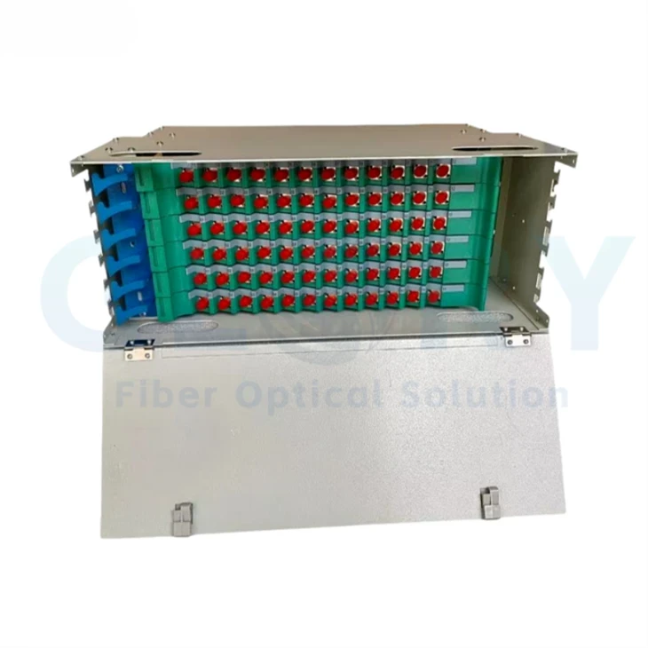

GL-ODF Fiber Optic Patch Panel
The GL-ODF is a 19-inch rack-mount fiber optic patch panel for backbone cable termination, splicing and patching at central offices and equipment rooms. Its housing uses 1.2 mm cold-rolled steel with electrostatic surface coating, a listed 482 × 260 mm footprint and 1U, 2U, 3U, 4U, 6U or 8U options. Select the modular splice/distribution arrangement, adapter panel and loaded fiber capacity for the required cross-connect and equipment connections.
|
|
Modular Splicing and Front-Side PatchingRack format: 19-inch compatible Housing: 1.2 mm cold-rolled steel, electrostatic surface coating Listed models: GL-ODF-12 through GL-ODF-144 Photograph shows an example GL-ODF assembly. Confirm the model, adapter arrangement and supplied module population for the order. |

Product Family: Rack-Mount Fiber Distribution and Patch Panels
The GL-ODF series provides a passive termination and patching point between incoming optical cables and optical communication equipment. Modular splice and distribution units support cable allocation, fiber organization and connection changes from the front of the rack.
Technical Specifications
|
Parameter |
Specification / configuration |
|---|---|
|
Dimensions |
482 * 260 * 1U/2U/3U/4U/6U/8U |
|
Material |
Cold-rolled steel plate |
|
Sheet Thickness |
1.2mm |
|
Surface Treatment |
Overall electrostatic spraying |
|
Installation Standard |
19-inch rack compatible |
|
Fiber Capacity |
12 to 288 fibers (depending on model) |
Capacity check: The family summary lists 12–288 fibers, while the model table below lists capacity entries from 12 to 144. Confirm the selected adapter format, adapter positions and loaded fiber terminations in the approved bill of materials. A 288-fiber assembly requires its own confirmed configuration.
GL-ODF Features and Fiber Management
Side Cable Entry with Front Operation
Side cable entry separates incoming cable routing from front-side patching work. Position the panel so technicians can reach the distribution units, cable retention points and patch cords from the planned service area. Confirm cable entry locations and rack clearance against the selected model drawing.
Modular Splicing and Distribution Units
Splice and distribution units can be arranged for the required project configuration. Match the initial module population to the selected rack height and connection schedule, and identify any positions reserved for later use. Keep the module type and loading on the purchase order for expansion planning.
Adapter Panels Matched to the Connector Format
FC, SC and ST adapter installation is described, and the ordering information also names SC simplex and LC duplex. Select the corresponding panel cutouts and retention parts. Confirm adapter type, polish and pigtail assembly before deciding the number of loaded fiber connections.
30-Degree Angled Front Adapters
The described front adapter arrangement uses a 30-degree angle to guide patch-cord exit direction. Check the space needed for connected plugs, cord routing and front-door access in the rack. Match the cable-management plan to the actual adapter panel supplied.
Cable Preparation, Protection and Retention
Cable stripping, protection and fixing provisions organize the transition from incoming cable to internal fibers and pigtails. Specify cable construction, strength-member retention, splice protection and fiber identification with the selected module arrangement so the installed cable can be managed without loading the fiber joints.
Internal Routing Radius Greater Than 40 mm
The internal routing design is described with a bend radius greater than 40 mm. Verify this condition in the loaded configuration. The selected feeder cable and patch cord must also follow their own specified bend limits, including the paths outside the panel.
Model and Ordering Guide
|
Model |
Listed size (mm / rack U) |
Listed capacity (fibers)* |
Weight (kg) |
Packing No. (pcs) |
|---|---|---|---|---|
|
GL-ODF-12 |
482 * 260 * 1U |
12 |
3.5 |
6 |
|
GL-ODF-24 |
482 * 260 * 2U |
24 |
4.6 |
4 |
|
GL-ODF-48 |
482 * 260 * 3U |
48 |
6.3 |
4 |
|
GL-ODF-72 |
482 * 260 * 4U |
72 |
8 |
2 |
|
GL-ODF-96 |
482 * 260 * 6U |
96 |
12.6 |
2 |
|
GL-ODF-144 |
482 * 260 * 8U |
144 |
15.4 |
1 |
* The supplied capacity heading groups SC simplex and LC duplex together. Confirm whether each entry describes fiber terminations or adapter positions for the selected panel; do not derive a doubled capacity without the approved loading schedule. All model values, sizes, weights and packing numbers above are retained as listed.
The packing number is separate from adapter quantity and fiber capacity. Confirm its carton or shipment basis with the quotation.
Configuration List and Packing Review
|
Component name as listed |
Listed quantity / configuration |
|---|---|
|
Mounting Ears |
2 pcs |
|
Integrated Module Fiber Splitter |
1~12 pcs (configurable as required) |
|
Integrated Module Handle |
1~12 pcs (configurable as required) |
|
Screws (M3 * 8) |
8 pcs (for mounting ears) |
|
Fusion Splicing Sleeves (12 fibers per sleeve) |
1~12 packs (configurable as required) |
|
Ribbon Protective Tube |
1~12 meters (configurable as required) |
Module terminology: Confirm whether the item named "Integrated Module Fiber Splitter" is a splice/distribution module or an optical splitter. If optical power splitting is required, specify the splitter circuit and ratio separately.
Splice protection: Confirm whether "12 fibers per sleeve" refers to a ribbon protector, a tray allocation or pack contents. Approve the protector type and the actual quantity required for the selected fibers. The listed ranges depend on the ordered configuration.
Application Planning for GL-ODF Patch Panels
Central Office and FTTH Backbone Termination
Backbone cable termination requires a managed transition from incoming fibers to equipment-facing patch cords. The GL-ODF provides splice and distribution units within a 19-inch rack format, with side cable entry and front operation for the patching area. Install it at the planned central-office or access-equipment rack and select the panel for the connector interfaces used by that equipment. Before ordering, confirm the model, rack height, cable construction, splice allocation, adapter format and pigtail population. Check actual loaded fiber capacity against the connection schedule and include a clear identification plan for each circuit.
Campus and Building Backbone Cross-Connects
A campus backbone may connect several building cables to a common equipment room, making cable assignment and later patching changes difficult without a documented layout. Use the GL-ODF as the rack-mounted termination and cross-connect point for the specified incoming cables and equipment patch cords. The modular arrangement allows the project to define its splice and distribution loading. Confirm cable entry paths, rack clearance, connector types, fiber identification and reserved module positions before procurement. Specify the initial loaded fiber count and the parts needed for planned expansion, rather than relying on the family capacity summary alone.
Metropolitan Network Equipment Rooms
A metropolitan network node needs accessible patching between backbone fibers and optical communication equipment while maintaining orderly cable routes. The GL-ODF series provides several rack heights and listed model capacities, with front-side operation and cable protection provisions for the termination area. Position the selected panel in the equipment rack with room for feeder routing and connected patch cords. Before ordering, approve the rack allocation, model dimensions, adapter and pigtail schedule, splice protection and cable-management arrangement. Include the required inspection documents and the correct packing basis when planning delivery of multiple panels to different network sites.
Selection and Project Ordering Details
|
Confirm before ordering |
Required project details |
|---|---|
|
Model and rack allocation |
Selected GL-ODF model, required U height, rack compatibility and installation clearance |
|
Capacity and adapter loading |
Actual fiber terminations, adapter positions, SC simplex / LC duplex or other approved panel format |
|
Connector and pigtail assemblies |
Interface, polish, fiber specification, pigtail length and circuit identification |
|
Cable entry and retention |
Incoming cable construction, entry direction, strength-member fixing and routing plan |
|
Module function and population |
Splice/distribution unit codes, initial loading and any separately specified optical splitter |
|
Splice protection and consumables |
Protector type, ribbon or single-fiber arrangement, pack contents and required quantity |
|
Mechanical and supply details |
Mounting ears, screws, handles, protective tubing, listed weight and packing-number basis |
|
Project documentation |
Approved assembly drawing, bill of materials, labels, sample review and inspection requirements |
Send Glory Optical the required GL-ODF model, loaded fiber count, connector schedule and rack drawing for configuration review. Include the module and accessory list with the quotation request so the supplied panel matches the planned termination layout.
About Glory Optical
|
Glory Optical facility, Ningbo |
Glory OpticalFounded in 2008 · Ningbo, China · OEM/ODM support Ningbo Glory Optical Communication Co., Ltd. manufactures passive fiber optic products and supplies telecom operators, ISPs, contractors, distributors and OEM/ODM buyers. Our portfolio covers fiber boxes, splice closures, PLC splitters, fiber optic cables, patch cords, pigtails, adapters, MTP/MPO assemblies and installation accessories for fiber network projects. Manufacturing & OEM/ODM SupportManufacturing capabilities across our product families include mold development, enclosure molding, component assembly and fiber cable assembly. OEM/ODM projects can cover drawings, product configuration, samples, branding, labels and packaging, according to the selected product and confirmed requirements. |

Testing Capabilities
Glory Optical supports inspection and testing according to confirmed product specifications and order requirements. The following videos show examples from our testing activities.
Water Spray Testing |
Sealing Performance Testing |
Water Resistance Testing |
Specification Review & Project Documentation
Before batch production, confirm the drawing or sample, product configuration, inspection requirements and packing details. For connectorized products, applicable inspection can include insertion loss, return loss and connector end-face checks. Datasheets, drawings and applicable test documents can be discussed for the order.
Discuss Your Product or Project Requirement
Send the product model, quantity, application and required configuration for quotation or sample discussion. Include any drawing, labeling, packaging and documentation requirements so our team can review the order details.
Email: sales@gloryoptic.com
Hot Tags: optical fiber patch panel, China optical fiber patch panel manufacturers, suppliers, factory, 24 port sc fiber patch panel, 96 port fiber patch panel, fiber optic panel, lc coupler panel, ofc patch panel, pre terminated patch panel


