LC to LC OM3 Duplex Fiber Optic Patch Cord
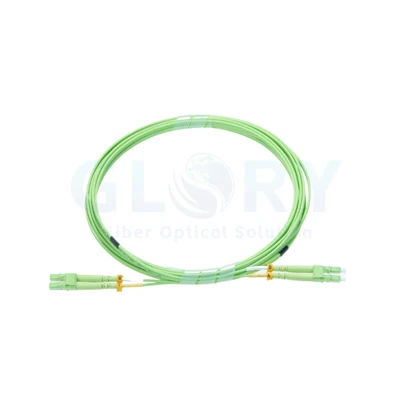
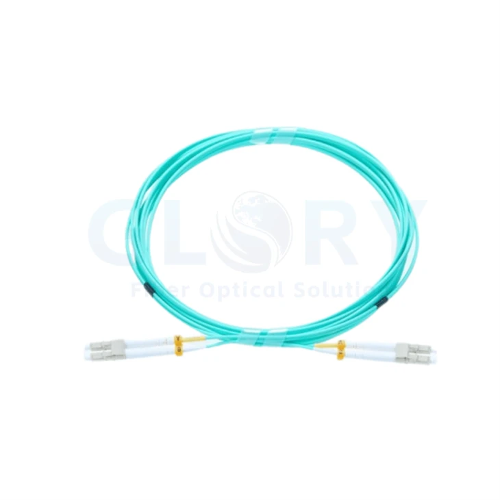
Plan a paired-fiber connection using the aqua LC assembly shown here. Two conventional LC terminations at each end provide a compact duplex patching format, with light-grey connector housings, separate white boots and A/B markers. The proposed Glory Optical configuration uses OM3 multimode fiber for compatible LC equipment and distribution ports.
Selection status: OM3, UPC finish and the 3.0 mm LSZH construction are proposed specifications, not measurements taken from the photograph. Confirm the fiber grade, build and performance requirements before placing the production order. Set the cable length from the intended route.

Aqua cable with light-grey LC bodies. OM3/UPC and construction data require sample or order confirmation. |
Aqua Cable, Light-Grey LC Housings and Two Separate BootsReference selection: OM3 50/125 μm · LC/UPC duplex · 3.0 mm LSZH · order-defined length The connector pairs keep the two optical positions together at the port. Distinct A/B markers assist circuit tracing, while the individual boots provide a separate exit for each cable leg. Review the fiber patch-cord range / Choose companion connection hardware |
Reference Data for the Proposed OM3 Assembly
| Characteristic | Proposed selection / reference data |
|---|---|
| Product name | LC to LC OM3 Duplex Fiber Optic Patch Cord |
| Selected fiber category | OM3 multimode, subject to sample approval |
| Core / cladding | 50/125 μm |
| Optical paths | 2 fibers, duplex |
| Termination selection | LC/UPC duplex at both ends |
| Jacket color | Aqua / turquoise |
| Pictured connector bodies | Beige / light grey, with separate white boots |
| Nominal diameter selection | 3.0 mm; confirm finished cable dimensions |
| Proposed jacket | LSZH |
| Cable length | To be specified for the measured route |
| Maximum connector insertion loss | ≤0.3 dB reference limit |
| Connector return loss | ≥30 dB reference limit |
| Effective modal bandwidth at 850 nm | 2000 MHz·km reference value |
| Static cable bend radius | ≥10 × finished cable OD; reference rule |
| Operating temperature | −20 to +70°C reference range |
Use this table to establish the part specification and acceptance plan. The published family values must be confirmed for the final build; neither aqua coloring nor a connector photograph identifies a tested optical grade.
Check Port Access with the Conventional Duplex Layout
| Part visible in the image | Detail for the installation |
|---|---|
| Paired LC housings | Two connector positions sit together at each endpoint. |
| Individual white boots | Each cable leg has its own supported exit from the connector. |
| Yellow A/B markers | The two positions can be distinguished during circuit checks. |
| Idle-end protective caps | Keep the interfaces covered until inspection and connection. |
| Aqua cable legs | Route the pair together with allowance around the connector exits. |
Review the sample against the actual adapter or equipment port, including neighboring connectors and the cable-management path. Verify room for operating the LC release and for the two boots to leave the patching field without pressure from a door, shelf or adjacent lead.
Record Positions as Well as Endpoint Names
Give the circuit two endpoint identifiers and record which LC position connects through each fiber. Follow those paths through the full patching route so a transmitter reaches the receiver assigned to it. A marker helps locate a position; a continuity check confirms where that fiber terminates.
| Path to record | Relationship to establish |
|---|---|
| First optical direction | Equipment 1 transmit position → equipment 2 receive position. |
| Second optical direction | Equipment 2 transmit position → equipment 1 receive position. |
Apply the Lead to a Compatible Multimode Connection
A duplex LC lead can serve the equipment end of a structured fiber route or a short local cross-connect. Confirm that the chosen optical interfaces accept the selected OM3 medium and the two-position LC arrangement.
| Connection task | Information needed |
|---|---|
| Equipment port to a fiber panel | The port type, selected pair and cable-management route. |
| Patching between distribution areas | Endpoint labels, required length and the installed fiber category. |
| Enterprise equipment-room connection | The optical device specifications and complete passive-channel budget. |
| Storage-system optical interconnect | The approved medium and duplex mapping for the particular storage equipment. |
Choose operating reach and data rate from the equipment documentation and the entire channel. A connector form factor does not establish which optical application is supported. Account for all fiber lengths and mating points when reviewing the link allowance.
Include suitable fiber patch-panel arrangements in the design, or discuss the full path with our data center connectivity support.
Specify the Length and Handling Requirements Together
Measure the route between the selected ports and state the overall-length reference points. Allow for the management path and service access. The photographed coil is an appearance view and does not establish a fixed cable length.
The starting construction is nominal 3.0 mm LSZH. Confirm its material details, complete dimensions and suitability for the installation space. For the reference static rule of ten times the finished diameter, a confirmed 3.0 mm diameter would require at least 30 mm radius; apply the final manufacturer-approved limits for the delivered build.
Obtain dynamic bending, handling-load and storage data separately where required. The −20 to +70°C operating range is a reference value to review with the ordered construction. Keep the cable supported, avoid compressed loops and prevent tension at the paired terminations.
Use the Agreed Test Setup to Evaluate Both Fibers
Start with Identification and End-Face Condition
Reconcile the cable label, length requirement and connector arrangement with the approved part record. Inspect the optical faces, clean when necessary and inspect again. Confirm both fiber paths before the lead becomes part of the working circuit.
Keep Component Limits Separate from the Channel Budget
The proposed connector targets are a maximum 0.3 dB insertion loss and a minimum 30 dB return loss. Agree the test wavelengths, multimode launch conditions and referencing method with those limits before testing. Retain results against the cable and individual fiber identifiers.
Evaluate the installed channel using its complete passive path. A satisfactory lead measurement is one part of that assessment; the other patching interfaces and routed fiber remain part of the operating loss budget.
Define the Aqua OM3 Cable for Quotation
| Enquiry item | What to provide |
|---|---|
| Equipment interfaces | LC port arrangement, multimode medium and optical equipment details. |
| Approved construction | OM3 glass, UPC termination, 3.0 mm LSZH selection and the retained duplex style. |
| Route dimensions | Required cable length and the points used to measure it. |
| Duplex position map | The two end-to-end connections required by the equipment and patching path. |
| Optical acceptance | Agreed insertion/return-loss limits, wavelengths, launch setup and reference method. |
| Installation limits | Final OD, static/dynamic bend allowances, loading and environmental ratings. |
| Supply documents | Part identifiers, sample approval, quantities, labels, packaging and result sheets. |
Use our project enquiry form to submit the endpoint details and selected construction. If a particular sample must be reproduced, include that requirement so the connector housings, boots and labels can be reviewed alongside the optical specification.
Discuss the Aqua OM3 Configuration Contact the Product Team
Glory Optical Cable and Component Supply
|
Ningbo Glory Optical production facility |
Fiber Assemblies from Our Ningbo OperationEstablished 2008 · Passive fiber connectivity · Custom assembly support Glory Optical supplies fiber connection products from Ningbo, China. Buyers can coordinate optical leads with adapters, pigtails, splitters and termination hardware within the product range. Our team supports discussions about standard products, project-specific assemblies and the details needed to define an OEM/ODM order. Establish the Accepted ConfigurationA clear cable definition links the intended circuit to the assembly that will be produced. For this aqua lead, establish the glass category, connector finish, cable construction and acceptance scope, then approve the sample or drawing that represents the order. The resulting record guides the applicable manufacturing and identification work. |

Examples of Enclosure Evaluation Work
The videos in this section demonstrate enclosure and closure evaluations from our wider range. Optical-lead acceptance should follow the checks specified for the cable itself, including end-face condition, continuity and loss measurements. Define those cable checks in the purchase record.
Water-Spray Test Example |
Seal-Check Video Example |
Water-Resistance Test Example |
Agree the Shipment Document Set
State which dimensional drawings, labels and optical records must accompany the goods. Carry the accepted part identifier through the order, packing details and requested test sheets. This gives receiving and installation teams a consistent record of the approved assembly.
Glory Optical Cable and Component Supply | Review an OEM/ODM Cable Project
Describe the LC Circuit and Required Lead
Tell us which two LC locations the cable will join and how it will be routed. Add quantity, desired length, the proposed OM3 construction and any marking or packing requirements. With these details, our team can review the build and discuss a quotation or sample.
Discuss Quantity and Pricing | Email Our Optical Product Team
Email: sales@gloryoptic.com
Hot Tags: lc to lc om3 duplex fiber optic patch cord, China lc to lc om3 duplex fiber optic patch cord manufacturers, suppliers, factory