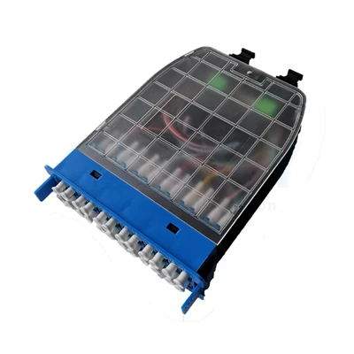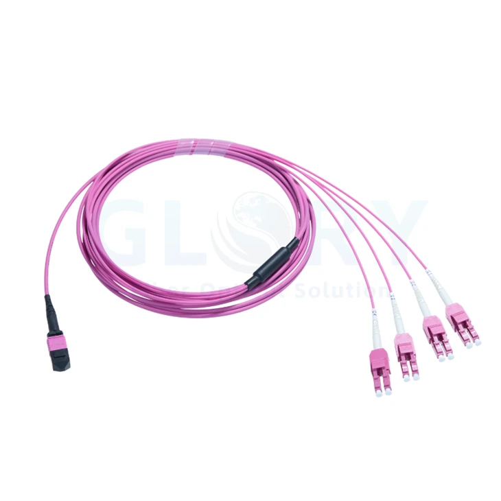
MPO to 4 LC Duplex Breakout Cable
Glory Optical's MPO to 4 LC Duplex Breakout Cable brings a Base-8 multi-fiber connection out to four individually accessible LC duplex branches. The 30 m OM4 assembly is intended for longer indoor routes between distribution points, racks and equipment areas. Its double-jacket trunk carries eight fibers, while the LC Uniboot terminations provide four two-fiber endpoints at the far end.

Specified build: one female UPC multi-fiber end, four LC UPC duplex Uniboot ends, 30 m OM4 trunk. |
One Trunk Route, Four Duplex Destinations30 m OM4 · 8 fibers · 1 MPO-compatible MTP®-8 female · 4 LC duplex Uniboot · Type B · OFNP Run the shared cable along the main pathway, then distribute its numbered LC branches at the equipment end. The 2.0 mm fanout legs help organize the final connections without routing four separate duplex cables along the full distance. |
Technical Data for the 30 m OM4 Assembly
| Assembly characteristic | Specified value |
|---|---|
| Product name | MPO to 4 LC Duplex Breakout Cable |
| Nominal assembly length | 30 m (approximately 98 ft) |
| Multi-fiber end | 1 × US Conec MTP®-8 Elite female (non-pinned), MPO interface |
| Duplex end | 4 × LC UPC duplex Uniboot connectors; 8 LC ferrules in total |
| Fiber population | 8 fibers, Base-8 |
| Fiber category | OM4 multimode, 50/125 μm |
| Optical wavelengths | 850 / 1300 nm |
| Fiber construction | Bend-insensitive glass fiber |
| End-face polish | UPC at the MTP® and LC ends |
| Assembly polarity | Type B |
| Jacket rating | Plenum (OFNP) |
| Sheath structure | Double jacket |
| Main cable OD | 3.6–4.5 mm, as specified for this product configuration |
| Fanout cable OD | 2.0 mm |
| MTP® end breakout length | 0.84 m |
| LC end breakout length | 0.91 m |
| MTP® connector insertion loss | ≤0.20 dB maximum |
| LC connector insertion loss | ≤0.20 dB maximum |
| MTP® connector return loss | ≥27 dB |
| LC connector return loss | ≥20 dB |
| Attenuation at 850 nm | ≤2.3 dB/km |
| Attenuation at 1300 nm | ≤0.6 dB/km |
| Minimum glass-fiber bend radius | 7.5 mm |
| Finished-cable bend allowance | 20D during movement / 10D at rest; D = cable OD |
| Long-term tensile load | 100 N |
| Short-term tensile load | 300 N |
| Operating range | −10 to +60°C (14 to 140°F) |
| Storage range | −10 to +70°C (14 to 158°F) |
The MPO and LC loss figures describe their respective connector limits. They are not a single 0.20 dB end-to-end cable guarantee. Calculate the installed channel from the applicable mated connections, the 30 m fiber segment and any intervening passive hardware.
Double-Jacket Construction for Shared Cable Routes

Construction illustration: two sheath layers around the fiber assembly, with aramid reinforcement. |
Separate the Trunk Path from the Final FanoutThe common trunk keeps the eight fibers together along the longer section of the installation. Inner and outer jackets surround the reinforced fiber assembly before it transitions into the end breakouts. The double sheath adds physical protection compared with a similar single-sheath construction. No numerical crush rating is specified here, so the cable still needs suitable pathway support and protection from tight clamps or tray edges. Set out the breakout locations before installation: the specified transition lengths are 0.84 m at the MTP® end and 0.91 m at the LC end. Include the connector access space when checking whether each end will reach its ports. |

Reference cross-section; layer dimensions are illustrative and are not a manufacturing drawing. |
Route the Finished Cable to Its Own Bend LimitsThe 7.5 mm minimum radius belongs to the glass fiber. For the assembled cable, use 20 times its outside diameter while moving it and 10 times its diameter once installed. For the published 3.6–4.5 mm main-cable range, those factors correspond to 72–90 mm during movement and 36–45 mm at rest. Confirm the delivered OD and any separate fanout-leg routing requirements with the order drawing. Long-term and short-term tensile ratings are 100 N and 300 N respectively. Plan the installation load through the cable support method rather than through the LC latches or the multi-fiber connector housing. |
Four Numbered LC Duplex Uniboot Branches

The LC end has four duplex connectors, numbered 1–4. Each duplex body contains two optical ferrules. |
Keep Each Pair Together at the Equipment EndA duplex Uniboot termination carries the two fibers of a branch through one compact cable entry. Four such terminations account for all eight fibers in this assembly; the branch numbers identify the four physical endpoints. Allocate one duplex branch to each intended duplex optical connection. Attach the cabinet and port identifiers to the cable schedule so technicians can locate an individual pair without disturbing the other three. The specified assembly is Type B. Confirm the complete MPO-position-to-LC-pair drawing and the transmit/receive assignment before installation; branch number alone does not establish which LC ferrule is Tx or Rx. |
| LC branch identification | Fiber allocation and connection check |
|---|---|
| Branch 1 | 2 fibers → one LC duplex endpoint; assign destination port and verify Tx/Rx. |
| Branch 2 | 2 fibers → one LC duplex endpoint; record its own port identifier. |
| Branch 3 | 2 fibers → one LC duplex endpoint; follow the approved wiring drawing. |
| Branch 4 | 2 fibers → one LC duplex endpoint; include both fibers in continuity testing. |
| Complete assembly | 4 duplex endpoints × 2 fibers = 8 fibers from the single Base-8 connection. |
The Multi-Fiber Connector at the Distribution End

Generic US Conec MTP® component illustration. Male and female alternatives are shown; this order uses one female Base-8 end. |
Match the Female UPC End to the Correct PortThe multi-fiber ferrule, housing key and retention parts form the MPO-compatible connection. Spring components support the ferrule inside the housing, with the rear crimp and boot completing the cable transition. The selected female end has guide holes rather than projecting alignment pins. It requires a compatible pinned UPC mating interface. The alternative male pin hardware in the exploded view is not an extra connector supplied with this cable. Verify the cassette or adapter interface, including gender and orientation, before ordering. The number of fibers populated in this Base-8 assembly comes from its configuration record, not from the generic component drawing. |
Select the Connection Architecture Before the Cable Route

Duplex interconnection example. The pictured equipment, optical modules and cassette are selected separately; the illustration does not establish device compatibility. |
Carry Four Duplex Connections Between Distribution AreasThe illustrated route places the common trunk between two cabinet areas. A compatible cassette presents the multi-fiber connection on one side, and four LC duplex branches reach the selected equipment ports on the other. Select the cassette wiring and pinned UPC interface for this female cable end. The four LC branches provide separate optical paths; the drawing depicts duplex interconnection rather than a guarantee of SR4 lane breakout. Equipment labels and speed examples in the reference topology describe that illustrated arrangement. Confirm your own module type, port configuration and channel budget before adopting a similar layout. |
| Use case | Planning requirement |
|---|---|
| Multi-fiber distribution to duplex equipment | Terminate at a suitable distribution interface, then take the four LC branches to compatible duplex transceiver ports. |
| Cabinet-to-cabinet or zone distribution | Use the 30 m trunk for the shared indoor pathway and position the end breakouts where branch access is needed. |
| Parallel-optics breakout | Use only when the optical modules, host port breakout mode and lane map support the intended split. The assembly provides passive fiber routing. |
| Patch-panel integration | Specify the correct panel and cassette hardware and include its internal wiring in the optical path. |
Duplex Distribution and SR4 Breakout Need Different Checks
Four LC duplex ends can serve four separate duplex optical links through an appropriate distribution arrangement. They do not by themselves make a higher-speed port split into four lower-speed ports. The installed transceivers and switching hardware determine that behavior.
For a compatible parallel-optics design, 40G SR4 to four 10G SR links or 100G SR4 to four 25G SR links can use an appropriate fiber fanout. Check the exact optics, supported switch breakout mode and position map. A duplex-only optical module requires its own matching duplex connection design, even if its aggregate data rate is similar.
Check the entire reach and loss budget for the chosen optics; 30 m is the cable assembly length, not a universal system reach rating. For help with pathway, port and module selection, review our data center connection planning services.
Commission Each Duplex Branch as a Separate Path
Inspect Both Connector Formats
Use inspection and cleaning tools suitable for the multi-fiber face at one end and LC ferrules at the other. Protect the unused branches while work continues on a single connection. A dust cap reduces handling exposure but does not replace inspection before mating.
Record the Port Assignment and Optical Results
Test all eight fibers against the approved Type B wiring record. For each numbered branch, document its destination, both fiber paths and the resulting Tx/Rx arrangement. Measure loss with the agreed multimode reference method and retain the per-path results.
Use the individual connector criteria in the technical table: MTP® IL ≤0.20 dB and RL ≥27 dB; LC IL ≤0.20 dB and RL ≥20 dB. Add the other channel components when assessing the complete link. Keep the test wavelengths, reference setup and acceptance scope in the inspection record.
Related Hardware for a Complete Fanout Installation
| Product family | How it relates to this cable |
|---|---|
| MTP/MPO assembly range | Compare connector-to-connector options and specify the correct fiber grade and end formats. |
| MPO/LC fanout cable family | The linked family example is OM3; request this OM4, four-duplex, double-jacket configuration explicitly. |
| MPO distribution panels | Plan rack mounting and the pinned UPC interface required by the female cable end. |
Quotation Details for the Four-Branch Build
| Item to confirm | Order requirement |
|---|---|
| Cable configuration | 30 m OM4 50/125 μm, 8 fibers, Type B, double-jacket OFNP. |
| Connector arrangement | One female UPC MTP®-8 / MPO end and four LC UPC duplex Uniboot ends. |
| End transitions | 0.84 m multi-fiber-side breakout and 0.91 m LC-side breakout; confirm measurement references on the drawing. |
| Interface drawing | MPO mating gender, full fiber-position map, LC branch numbers and Tx/Rx port assignment. |
| Installed equipment | Destination modules, panel or cassette model, host breakout support where applicable. |
| Shipment requirements | Cable quantity, identification format, inspection records, packaging and requested delivery date. |
Send the route drawing and four destination port names to Glory Optical when requesting a quotation. Note any required change to length, jacket or end configuration so it can be reviewed as a separate build. Discuss the connection details before the cable schedule is approved.
Request Four-Branch Cable Pricing Browse Indoor Data Center Cabling
MTP® is a registered trademark of US Conec Ltd. Component and layer illustrations explain the construction concept; the confirmed order drawing defines the supplied assembly.
About Our Manufacturing Business
|
Glory Optical facility in Ningbo, serving fiber connectivity projects |
Ningbo Glory OpticalPassive optical products · Ningbo, China · Operating since 2008 Ningbo Glory Optical Communication Co., Ltd. works with distributors, installation contractors, network operators and equipment suppliers on passive fiber products. Cable assemblies are part of a broader range that includes patching accessories, optical adapters, splitters, fiber boxes and splice closures, allowing the project discussion to cover both the connection and its installation hardware. Confirm a Sample, Then Fix the Build RecordFor a fanout order, establish the connector formats, fiber grade, branch labeling and inspection requirements around a sample or drawing. Product-dependent manufacturing work spans cable termination, component assembly, enclosure molding and mold development. Brand marks, labels and packing can be included in an OEM/ODM specification once the details are agreed. |

A View of Our Enclosure Test Facilities
The three videos below concern enclosure products in our wider range. They illustrate water and sealing evaluations, while this fiber cable requires its own continuity, branch mapping, connector inspection and optical performance records. Select those cable checks explicitly in the purchase specification.
Water Spray Evaluation |
Seal Performance Evaluation |
Water Resistance Evaluation |
Documents to Match the Delivered Cable
Keep the approved drawing and branch schedule with the order record. Agree which configuration sheets and inspection results are needed, how cable identifiers will appear and what the packaging must protect. The resulting documents should describe the actual MPO-to-LC build and its accepted measurement procedure.
About Our Manufacturing Business | OEM/ODM Project Enquiries
Start with the Rack and Port List
Provide the required number of cables together with rack locations, MPO interface details and the four LC destinations. Add the planned route length and any special identification requirements. We can use that information to review the assembly and discuss sample availability, packing and the delivery requirement.
Request Project Pricing | Contact the Sales Team
Email: sales@gloryoptic.com
Hot Tags: mpo to 4 lc duplex breakout cable, China mpo to 4 lc duplex breakout cable manufacturers, suppliers, factory, data center cabling, data center fiber cabling, Mpo 12 Fiber Cable, Mtp Mpo Fiber, Mtp Mpo Fiber Breakout Cable, Mtp To Lc Breakout Cable