LC to LC OM4 Duplex Fiber Optic Patch Cord
A magenta duplex lead with conventional LC connector pairs provides an organized connection between two LC patching points. The proposed Glory Optical build uses OM4 multimode fiber and an LC/UPC interface at each end, with two optical paths carried through the assembly. It is intended for equipment-room and cabinet projects specifying a duplex OM4 connection.
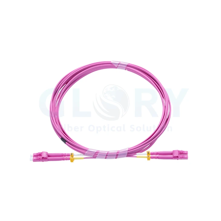
Selection status: the OM4 grade, UPC finish, 1 m length and 2.0 mm LSZH construction below are proposed specifications. Approve them against a sample and part drawing before placing the production order. The photograph establishes the visible connector style and color; it does not verify those hidden specifications.

Shown: magenta LC duplex style. OM4/UPC and cable ratings remain subject to build approval. |
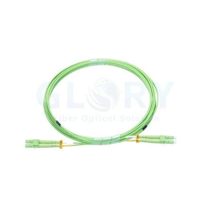
Conventional Duplex Connectors with Separate BootsProposed configuration: OM4 50/125 μm · LC/UPC pair at each end · 1 m · 2.0 mm LSZH The pictured lead has two LC bodies retained together at either end, individual cable-entry boots and visible A/B markers. This format provides direct access to the paired terminations when tracing a circuit or checking a connector. Browse LC and other patch-cord assemblies / Find optical connection products |
Proposed OM4 Configuration for Approval
| Selection item | Reference value / approval requirement |
|---|---|
| Product designation | LC to LC OM4 Duplex Fiber Optic Patch Cord |
| Optical selection | OM4 multimode - proposed build |
| Fiber dimensions | 50/125 μm - reference selection |
| Fiber quantity | 2 optical fibers, duplex |
| End A | LC duplex; UPC finish proposed for approval |
| End B | LC duplex; UPC finish proposed for approval |
| Assembly length | 1 m reference configuration; final measurement to be agreed |
| Nominal cable diameter | 2.0 mm reference selection; confirm the finished dimensions |
| Outer jacket | LSZH reference construction; material specification to be approved |
| Visible color | Magenta / purple-pink cable and connector housings |
| Operating temperature | −20 to +70°C reference range; validate for the final build |
| Optical acceptance | Insertion-loss and return-loss limits to be specified for the ordered assembly |
These values define a starting configuration for quotation. The approved drawing and purchase specification must establish the actual cable supplied. Connector colors alone do not establish polish or fiber performance.
Keep the Connector Pair and Cable Exits Accessible
| Observed feature | Practical role |
|---|---|
| Two LC bodies per end | Provide separate optical positions for a duplex interface. |
| Duplex retaining piece | Holds the connector pair in its working arrangement. |
| Two individual boots | Protect the transitions from the paired cable legs into the terminations. |
| A/B identification markers | Help distinguish the two positions when checking the circuit map. |
| Protective end caps | Cover idle interfaces until inspection and mating. |
Check the physical sample for latch access and spacing at the intended ports. Allow room for the boots to exit without being pressed against a cabinet door or cable manager. Retain the conventional connector arrangement shown when reviewing the approved build.
Confirm the Pairing through the Entire Channel
Map each LC position from the first endpoint to the second, including any adapters or intermediate patch panels. Match the resulting paths to the transmit and receive assignments of the connected optical equipment. The A/B markers are useful for tracing, but the cable's measured continuity establishes the actual map.
| Direction to establish | Required optical relationship |
|---|---|
| Equipment A → equipment B | A-side transmitter reaches the corresponding B-side receiver. |
| Equipment B → equipment A | B-side transmitter reaches the corresponding A-side receiver. |
Choose the Link before Assigning the Cable
Use a duplex OM4 lead where the equipment specifies an appropriate LC multimode interface. Typical planning tasks include local equipment-to-panel patching, cabinet cross-connects and paired-fiber links in enterprise or telecommunications rooms.
| Installation location | Review before release |
|---|---|
| Optical equipment to a distribution panel | Connector geometry, fiber category, port assignment and service access. |
| Adjacent patching fields | Measured length, paired-fiber continuity and label correspondence. |
| Data cabinet or LAN equipment room | Compatible optics, allowed channel loss and the selected jacket requirements. |
| Storage-network optical path | The equipment's supported medium, interface and reach for that particular link. |
An OM4 designation does not determine a universal operating speed or distance. Check the selected transceiver's interface and channel allowance, including all patch leads, panels and the installed fiber length.
Coordinate the connection with fiber distribution-panel products, or request a review through our data center fiber cabling service.
Set the Jacket and Dimensions around the Route
The starting selection is a 1 m magenta lead with an LSZH jacket and nominal 2.0 mm cable size. Confirm the exact dimensions and length references on the assembly drawing; the coiled product photograph provides neither a length measurement nor a material verification.
Choose the jacket for the installation requirements and approve its material documentation. Establish the completed cable's minimum bending radius and handling limits before routing. Support both cable legs without tight ties, sharp transitions or load on the LC latches.
The proposed operating range is −20 to +70°C, subject to confirmation for the chosen construction. Specify storage conditions separately if they are needed for shipment or inventory planning.
Agree Optical Tests against the Ordered Assembly
Inspect the Ends and Check Both Paths
Examine the interfaces before mating. Clean and inspect again when necessary, then confirm that each fiber reaches its intended far-end position. Keep the measured pairing associated with the cable identifier and the approved drawing.
Write the Pass Limits into the Part Record
State insertion-loss and return-loss requirements together with the measurement wavelengths, multimode launch conditions and reference method. No numeric optical guarantee is assigned from the photograph. Request the relevant results for the specific approved assembly.
For installation acceptance, evaluate the complete path in addition to the individual lead. This keeps the component measurements tied to the connection that will carry the operating signal.
Approve the Magenta OM4 Build before Production
| Approval topic | Details needed |
|---|---|
| Fiber and finish | Approve the OM4 glass specification and LC/UPC termination at both ends. |
| Length and route | Agree overall measurement points, installed reach and allowance at the ports. |
| Cable construction | Confirm LSZH material, nominal 2.0 mm dimensions and the paired-cable layout. |
| End-to-end pairing | Provide an LC position map that completes the required transmit/receive paths. |
| Performance record | State optical limits, test wavelengths, multimode launch conditions and required result sheets. |
| Mechanical / environmental data | Obtain finished-cable bend limits, handling load, temperature ratings and storage conditions. |
| Production identification | Set cable labels, quantities, packing and any approved sample references. |
Share the intended endpoints and proposed configuration with Glory product sales. A quotation can identify the selected materials and required test scope; the sample and drawing should resolve the remaining construction details before manufacture.
Enquire about This OM4 Selection View the Patch-Cord Range
Glory Optical Project and Manufacturing Support
|
Glory Optical facility, Ningbo |
Ningbo Fiber Connectivity SupplyOperating since 2008 · Passive optical products · Project assembly discussions Based in Ningbo, Glory Optical supports network procurement with passive fiber products and assembly discussions. The product range includes optical leads, connector components, adapters, pigtails and splitters, together with fiber termination and protection hardware. Customers can review a standard configuration or develop a custom part definition with our team. Turn the Selected Parameters into a Part RecordFor the proposed magenta lead, turn the fiber, jacket, connector and test selections into a controlled assembly description. Agree which sample or drawing establishes the final version. That record can then guide the applicable termination, assembly, labeling and packing work for the order. |

Testing Examples from Our Product Range
These evaluations show fiber enclosure and closure products. The patch cord requires its own agreed optical and mechanical acceptance checks. Keep the cable test requirements within the assembly specification so enclosure demonstrations are not used as evidence of cable performance.
Enclosure Spray Demonstration |
Closure Seal Demonstration |
Enclosure Water Demonstration |
Connect the Approval Documents to the Shipment
Prepare a document list for the shipment: for example, the accepted part drawing, material selection, label record and requested optical results. Use consistent identifiers so the receiving team can reconcile the cable with the version that was approved for production.
Glory Optical Project and Manufacturing Support | Discuss Custom Production
Share Your Duplex Patching Plan
Provide the LC endpoint arrangement, desired quantity and route length, then identify the proposed OM4 and jacket selections. Include any sample-review, marking or packing requirements. Those details let our team discuss a clear build definition and the corresponding supply arrangements.
Enquire about Order Pricing | Reach Our Supply Team
Email: sales@gloryoptic.com
Hot Tags: lc to lc om4 duplex fiber optic patch cord, China lc to lc om4 duplex fiber optic patch cord manufacturers, suppliers, factory, data center cabling, data center fiber cabling, Mpo 12 Fiber Cable, mtp mpo, Mtp Mpo Fiber, Mtp To Lc Breakout Cable