Finish the Single-Mode Route at the Equipment Port

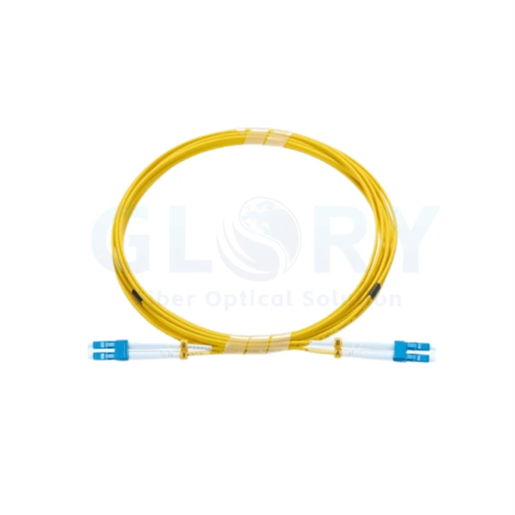
Pictured hardware: blue LC pairs on yellow cable. Proposed OS2/UPC ratings await build approval. |
LC UPC to LC UPC Duplex OS2 Fiber Patch CordUse a removable pair at a single-mode transmitter or receiver when the permanent route terminates in a distribution field. Yellow zipcord separates into two white boots behind each blue LC housing pair. This layout suits front-access patching where the fixed plant stays in place during equipment changes. Yellow sheath · two optical paths · separate white boots · visible position markers Build an OS2 Spare Specification Inspect the Reference Ratings |
Reference build awaiting approval: OS2 9/125 μm with LC/UPC ends and nominal 2.0 mm PVC/OFNR cable. The photo identifies the visible style; verify glass, finish, jacket and test limits against the accepted sample. Length follows the required route.
Read the Reflection Figure in the Right Direction
At a single-mode connection, two different questions matter: how much forward power is lost, and how much light travels back toward the source. Insertion loss addresses the first question; connector return loss addresses the second.
The proposed UPC target is at least 50 dB return loss. A larger positive return-loss reading represents a smaller reflected fraction; the corresponding connector reflectance uses a negative sign. Keep the metric and sign explicit on the test sheet.
A whole-channel optical return-loss measurement also includes contributions elsewhere in the path. Specify whether acceptance concerns the patch-cord interfaces or the installed route, then select the appropriate test method. A component target does not describe every reflection seen by the transmitter.
OS2 Build Sheet - Values for Engineering Review
| Property | Reference selection |
|---|---|
| Designation | LC UPC to LC UPC Duplex OS2 Fiber Patch Cord |
| Transmission medium | OS2 single mode, 9/125 μm |
| Selected glass | G.657.A1 |
| Termination | LC/UPC at either side; duplex arrangement |
| Fiber population | 2 independent optical fibers |
| Nominal cable size | 2.0 mm |
| Sheath selection | PVC / OFNR |
| Appearance | Yellow jacket, blue connector bodies, white boots |
| Reference wavelengths | 1310 nm and 1550 nm |
| Insertion-loss objective | ≤0.3 dB production target |
| UPC return-loss objective | ≥50 dB |
| Fiber attenuation at 1310 nm | ≤0.36 dB/km |
| Fiber attenuation at 1550 nm | ≤0.22 dB/km |
| In-service temperature | −20 to +70°C |
| Storage conditions | −40 to +80°C |
| Requested length | Order-defined; agree the length datums |
| Position correspondence | A-to-B reference arrangement; verify for the selected circuit |
Treat these entries as design inputs until the part record is accepted. Fiber attenuation is stated per kilometre; insertion loss describes a different contribution. Combine the relevant quantities with the other passive elements when assessing the operating channel.
Decide What the Local Lead Must Accommodate
A Single-Mode Interface at Both Destinations
Check the equipment documentation for medium, wavelengths and LC finish. For a two-fiber optical interface, retain the required relationship between the transmit and receive positions through the distribution field. The blue housing is a visual cue; the port specification establishes the mating interface.
Space for a Serviceable Equipment Connection
Locate the removable lead between the active port and the relevant distribution-panel position. Measure along the management route, with room to release the connector and move the equipment as planned. A coil in a product image provides no length reference.
An Optical Budget for the Complete Route
Check the selected optics against all installed fiber and connections, including the building or campus segment beyond the cabinet. OS2 glass alone does not assign a transmission distance. For a multi-location project, request single-mode cabling coordination with the actual endpoint list.
Replace a Lead without Losing the Circuit Identity
- Record the device port and distribution position before removing the existing lead. Retain the pair orientation in that record.
- Compare the replacement's part label, finish and sheath with the circuit requirement. Inspect its interfaces and address contamination before connection.
- After the change, verify the intended service and retain the relevant optical readings. Associate the replacement identifier with the port record rather than relying on color alone.
Keep both boots free of side pressure once the connector is seated. Use the finished-cable bending and handling allowances from the accepted build, and arrange spare length where it remains accessible during later changes.
Order a Matched Spare, Ready for Its Assigned Port
A useful spare has a defined destination: record the two port IDs, required routed length, sheath requirement and accepted loss targets. Add a sample reference if the blue housings, white boots or label arrangement must be reproduced.
Send those details to Glory technical sales or use the quotation request. Other patch-lead formats and optical mating components can be reviewed alongside the spare requirement.
Glory Optical: A Defined Part for Repeat Purchasing

Ningbo production facility |
Keep the Replacement Specification AvailableGlory Optical has operated in Ningbo since 2008. For recurring lead orders, a consistent part description helps buyers request the same connector arrangement, cable construction and identification on a later purchase. |
Demonstrations from the Enclosure Range
These three videos concern boxes and closures. Evaluate the OS2 lead using its own agreed optical and mechanical criteria.
Enclosure spray trial |
Closure sealing trial |
Enclosure immersion trial |
Hot Tags: lc upc to lc upc duplex os2 fiber patch cord, China lc upc to lc upc duplex os2 fiber patch cord manufacturers, suppliers, factory