

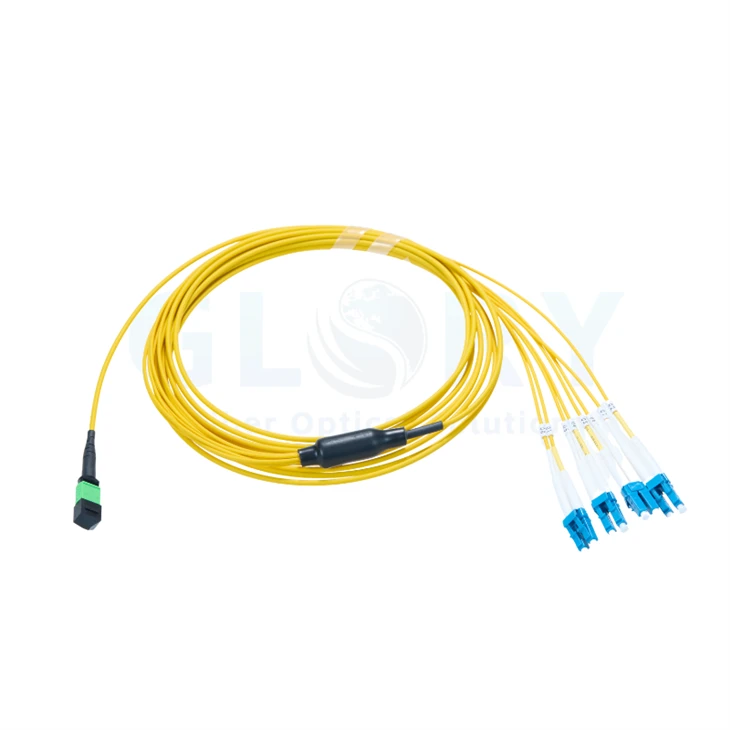
OS2 MPO to 4 LC Duplex Breakout Cable
Specify a single-mode fanout when one multi-fiber distribution port must serve four duplex LC circuits. Glory Optical's OS2 MPO to 4 LC Duplex Breakout Cable carries eight G.657.A1 fibers through a 30 m double-jacket trunk. The distribution end is a female MTP®-8 APC interface; the equipment end presents four LC UPC duplex Uniboot connections.
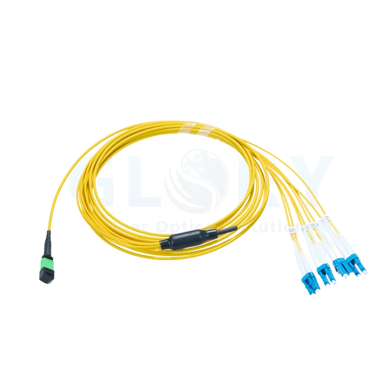
Glory MPO/LC series reference: pictured multimode six-duplex assembly. This page specifies an OS2 four-duplex cable; fiber grade, connector finish and branch count follow the confirmed order. |
A Single-Mode Schedule for Four Duplex CircuitsOS2 9/125 μm · 30 m · 8 fibers · female APC multi-fiber end · 4 LC UPC duplex ends · Type B Choose the common trunk for the distribution route and reserve the individual LC legs for the final port assignments. Both optical faces in each duplex branch belong to the same circuit, giving four independently documented two-fiber paths. |
Rated OS2 Configuration and Optical Limits
| Specification field | OS2 assembly value |
|---|---|
| Product designation | OS2 MPO to 4 LC Duplex Breakout Cable |
| Assembly length | 30 m (approximately 98 ft) |
| MPO-compatible termination | 1 × US Conec MTP®-8 Elite female, non-pinned |
| LC termination | 4 × LC duplex Uniboot; 8 LC ferrules |
| Optical medium | OS2 single mode, 9/125 μm |
| Populated fiber count | 8 fibers / Base-8 |
| Glass specification | G.657.A1 bend-insensitive fiber |
| Reference wavelengths | 1310 nm and 1550 nm |
| MTP® end polish | APC |
| LC end polish | UPC |
| Wiring designation | Type B |
| Cable sheath | Double-jacket construction, Plenum (OFNP) |
| Trunk outside diameter | 3.6–4.5 mm |
| Branch outside diameter | 2.0 mm |
| MTP® side transition length | 0.84 m |
| LC side transition length | 0.91 m |
| MTP® maximum insertion loss | ≤0.35 dB |
| LC maximum insertion loss | ≤0.20 dB |
| MTP® minimum return loss | ≥65 dB |
| LC minimum return loss | ≥55 dB |
| Fiber attenuation, 1310 nm | ≤0.35 dB/km |
| Fiber attenuation, 1550 nm | ≤0.21 dB/km |
| Minimum radius of the glass fiber | 10 mm |
| Routing radius of the finished cable | 10D moving / 5D stationary; D = cable outside diameter |
| Rated tensile load, sustained | 100 N |
| Rated tensile load, short duration | 300 N |
| Service temperature | −10 to +60°C (14 to 140°F) |
| Storage temperature | −10 to +70°C (14 to 158°F) |
Apply each loss limit to its stated connector format using the agreed measurement procedure. Assess the completed optical path with its other mated interfaces, distribution hardware and fiber sections included in the channel budget.
One APC Multi-Fiber End, Four UPC Duplex Ends

Connector alignment illustration (FOA). Gender and keying are shown; polish is specified separately. |
Check Gender and End-Face Geometry IndependentlyAt the distribution side, select a pinned mating connection suitable for the specified female APC end. The guide holes receive the counterpart pins; the adapter's key arrangement and port orientation must also match the planned route. At the four destinations, the LC optical faces use UPC polish. Confirm matching LC UPC receptacles on the selected equipment. The cable's APC and UPC designations refer to different ends of the same assembly and must remain distinct in the port schedule. Record the actual receptacle type before allocating stock. Housing color can assist identification, but interface records and the approved assembly drawing establish the required gender, polish and fiber layout. |
How the Multi-Fiber End Is Assembled

US Conec hardware reference showing alternative male and female parts. Only the female configuration applies to the specified distribution end. |
Follow the Load Path from Housing to Cable ExitThe keyed outer housing retains the connector at the distribution interface. Inside, the ferrule carries the populated fiber positions and works with a spring-supported internal mechanism to form the optical connection. The diagram includes pin spacers and clamps for different connector variants. Use it to understand the hardware families; the eight populated fibers and APC finish are established separately by the OS2 specification. The rear retention and boot support the transition into the cable. Release the connector using its intended latch mechanism and support the cable behind the boot when routing or changing a connection. |
| Assembly area | What to confirm |
|---|---|
| Ferrule and guide-hole area | APC finish, female configuration and the specified eight-fiber population. |
| Key and retaining housing | Correct orientation for the selected adapter or cassette port. |
| Spring and internal retention | Use the approved connector configuration; avoid field changes to its internal parts. |
| Boot, transition and outer sheath | Provide support without concentrating load at either connector exit. |
Assign Four LC Circuits Before Patching
Each duplex connector groups two LC ferrules into one endpoint. Across the assembly, four endpoints account for eight optical paths. Give each pair a circuit identifier tied to its rack, equipment and port; specify any production branch numbering in the order record.
| Circuit entry | Information to record |
|---|---|
| Duplex circuit A - 2 fibers | Destination rack and LC UPC port; identify its two fiber paths on the approved mapping. |
| Duplex circuit B - 2 fibers | Destination equipment and LC pair; confirm the transmit/receive relationship. |
| Duplex circuit C - 2 fibers | Port label and inspection result for each of its two ferrules. |
| Duplex circuit D - 2 fibers | Port assignment and optical test record for the remaining pair. |
| Common distribution end | One Base-8 connection serving all four circuits; Type B map to be supplied with the configuration. |
The A–D entries above are planning identifiers, not a claim about factory label characters. Obtain the end-to-end fiber-position drawing to associate every multi-fiber position with its destination LC ferrule. Verify the complete Type B arrangement through any additional passive components.
Integrate the Fanout into the Distribution System

Modular distribution concept (FOA). This diagram shows system architecture; the four-LC cable geometry is defined in the order drawing. |
Start with the Single-Mode Distribution InterfaceA suitable cassette or distribution adapter can place the multi-fiber interface at the managed patching point. Review its internal wiring, single-mode fiber specification and pinned APC mating connection as part of the same design. Take the four LC UPC branches to their assigned single-mode equipment ports. Decide where the fanout transition will sit so the individual legs reach the ports without hanging across adjacent hardware. Use the MPO panel and cassette range to discuss the mounting arrangement. Confirm the exact loaded interfaces and fiber mapping rather than treating the panel enclosure alone as the optical specification. |

Rack cable-management example (NHLink). Colors and connector combinations shown illustrate routing; refer to the OS2 specifications for this assembly. |
Measure the Managed Route and the Two End TransitionsFor cabinet-to-cabinet or zone wiring, measure the supported pathway together with both end access areas. The nominal assembly length is 30 m, with stated breakout lengths of 0.84 m at the multi-fiber side and 0.91 m at the LC side. The double jacket surrounds the shared cable section, while 2.0 mm branch legs allow the final terminations to be organized individually. Choose supports that protect the sheath and keep the connectors accessible for inspection and removal. Review equipment locations and the expected service moves with our fiber cabling project team. Define any changed transition length or cable construction on a separate drawing. |
Select Optics for the Complete Single-Mode Channel
Use compatible single-mode optical modules at the two ends of each circuit. Optical wavelength, transmit/receive characteristics, interface polish and the full loss budget determine whether the planned equipment connection is suitable. The cable passively routes the fibers; a split-port application additionally requires the appropriate module lanes and host configuration.
Keep the 30 m cable length separate from the equipment's permitted system reach. At the stated maximum fiber attenuation, the glass contribution over 30 m is approximately 0.0105 dB at 1310 nm or 0.0063 dB at 1550 nm. Those calculated values exclude connector and distribution-component losses.
Installation Allowances for the OS2 Cable
The finished assembly has its own routing limits: 10 times the cable diameter during movement and 5 times the diameter when stationary. With the specified main-cable OD range of 3.6–4.5 mm, that gives 36–45 mm moving and 18–22.5 mm stationary. Check the delivered diameter and the requirements of each transition area on the drawing.
The 10 mm glass-fiber radius is a separate fiber rating. Lay out the jacketed route using the finished-cable allowance. Sustained and short-duration tensile ratings are 100 N and 300 N; establish an installation method that transfers load through suitable cable support rather than through the LC bodies.
Select the OFNP double-jacket assembly for the confirmed indoor installation requirement. The stated operating range is −10 to +60°C, with storage from −10 to +70°C. Include any unusual pathway exposure or handling condition in the configuration review.
Accept the Eight Optical Paths with Traceable Results
Inspect One Multi-Fiber Face and Eight LC Ferrules
Prepare tools for both connector formats and for the specified APC or UPC face. Inspect and clean the interfaces before making a connection, including the equipment-side mating faces. Keep the other LC pairs protected while a single circuit is being installed or tested.
Separate Wiring Verification from Loss Measurement
First trace continuity from the female multi-fiber end to every LC endpoint and compare the result with the approved Type B position map. Then test with suitable single-mode reference leads, agreed wavelengths and a documented reference setup. Retain results against the circuit identifiers used in the rack schedule.
The OS2 connector criteria are MTP® insertion loss ≤0.35 dB and return loss ≥65 dB, with LC insertion loss ≤0.20 dB and return loss ≥55 dB. State whether the requested report covers individual interfaces or the installed end-to-end channel so acceptance records can be interpreted correctly.
Coordinate the Cable with the Rest of the Rack
| Glory product or service | Selection point |
|---|---|
| Multi-fiber connection products | Discuss APC distribution interfaces and the required OS2 fiber arrangement. |
| MPO-to-LC assembly family | The linked example is multimode. Specify OS2, four duplex ends and the requested single-mode loss limits for this order. |
| Patch-panel options | Coordinate rack mounting, cable management and the populated optical interfaces. |
Information Needed to Release an OS2 Order
| Review item | Required detail |
|---|---|
| Specified assembly | 30 m; OS2 9/125 μm; G.657.A1; eight fibers; double-jacket OFNP. |
| Connector schedule | One MTP®-8 female APC end and four LC UPC duplex Uniboot endpoints. |
| Routing and transitions | Main OD, branch OD, transition measurements and the pathway drawing. |
| Position record | Type B fiber map plus the four destination circuit labels. |
| Test documentation | Single-mode reference method, wavelengths and agreed IL/RL acceptance scope. |
| Production and delivery | Quantity, label layout, packing, required documents and delivery date. |
Send your four-circuit port list with the proposed distribution hardware to Glory Optical. We can review the interface requirements and confirm the drawing, sample and supply details before the configuration is released.
Request OS2 Fanout Cable Pricing View More Fiber Connectivity
MTP® is a registered trademark of US Conec Ltd. Product-family photographs and generic connector diagrams illustrate construction and routing concepts. The approved drawing defines the supplied OS2 assembly.
Glory Optical Manufacturing and Supply
|
Glory Optical's manufacturing facility in Ningbo, China |
Your Fiber Connectivity SupplierNingbo operation established in 2008 · Passive fiber components and assemblies From our base in Ningbo, Glory Optical supports fiber network buyers with passive connectivity and installation products. We work with service providers, contractors, distribution partners and OEM/ODM customers. The range includes terminated cables, adapters, pigtails, PLC splitters, fiber boxes and splice closures for different parts of the network. Set the Production Requirements with the SampleAn order review turns the requested interfaces and routing into a defined assembly. Confirm the sample, optical configuration, cable identification and packing requirements before production. Depending on the product, our work includes fiber assembly, component assembly, molded enclosures and tooling development; OEM/ODM details are agreed against the selected item. |

Testing Across Our Product Range
These retained company videos demonstrate water-related testing of enclosures and closures. The OS2 fanout is assessed through cable-specific inspection and measurement records, including connector faces, continuity, circuit routing and optical performance. Agree the relevant checks for this cable with the order.
Enclosure Spray-Test Example |
Closure Sealing-Test Example |
Enclosure Immersion-Test Example |
Keep the Configuration and Inspection Record Together
Ask for the documents needed by the installation team while the build is being reviewed. Tie the assembly drawing, label schedule and applicable test results to the same configuration. Define the measurement method and packing instructions so the receiving team can check the supplied cable against the agreed record.
Glory Optical Manufacturing and Supply | OEM/ODM Configuration Support
Discuss the Single-Mode Connection Plan
Share the planned distribution interface, the four LC equipment ports and the number of assemblies required. Include the route length, drawing references and any identification or packaging detail. Our team can then discuss the requested single-mode build, sample review and delivery arrangements.
Ask for a Quotation | Email Our Team
Email: sales@gloryoptic.com
Hot Tags: os2 mpo to 4 lc duplex breakout cable, China os2 mpo to 4 lc duplex breakout cable manufacturers, suppliers, factory, data center cabling, data center fiber cabling, Mpo 12 Fiber Cable, mtp mpo, Mtp Mpo Fiber Breakout Cable, Mtp To Lc Breakout Cable


