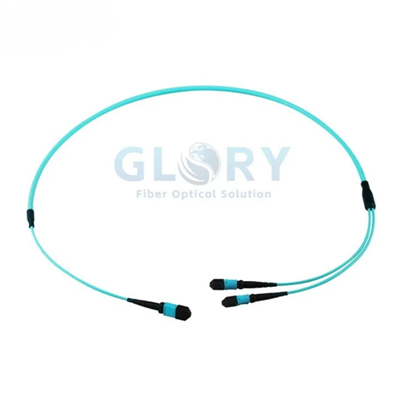

MPO to MPO Fiber Patch Cord
Glory Optical's MPO to MPO Fiber Patch Cord provides a configurable OS2 single-mode connection for data center, cabinet and backbone cabling. Choose the fiber count, cable length, jacket, connector gender, polarity and pulling-eye arrangement to match the channel plan. The series uses G.657.A1 9/125 μm fiber and APC interfaces, with a maximum insertion-loss specification of 0.35 dB.
|
OS2 cable configuration example with protective caps. Connector quantity and breakout layout depend on the selected fiber count. |
Configure the OS2 Assembly for Your NetworkProduct line: Data Center Cabling / MTP®/MPO Assemblies OS2 · 8–288 fibers · APC · Female / male options · Type A / B / C Select the connectorized assembly as a complete configuration. Higher fiber counts use multiple 12-fiber branches; cable diameter and branch quantity follow the selected construction. |

Technical Specifications
| Parameter | Specification |
|---|---|
| Product name | MPO to MPO Fiber Patch Cord |
| Fiber mode / core and cladding | OS2 single-mode, 9/125 μm |
| Glass fiber | G.657.A1 bend-insensitive fiber |
| Fiber count options | 8, 12, 24, 36, 48, 72, 96, 144 or 288 fibers |
| Cable length | Custom length; specify the required finished length with the order |
| Connector A | US Conec MTP®-12 Elite, female (non-pinned) or male (pinned) |
| Connector B | US Conec MTP®-12 Elite, female (non-pinned) or male (pinned) |
| Polish | APC to APC |
| Polarity options | Type A straight-through / Type B cross / Type C crossed pairs |
| Cable jacket options | Plenum (OFNP) / LSZH / Riser (OFNR) |
| Trunk outside diameter | 3.0–23.0 mm, depending on fiber count and cable construction |
| Wavelengths | 1310 / 1550 nm |
| Insertion loss | ≤0.35 dB maximum |
| Return loss | ≥60 dB |
| Fiber attenuation at 1310 nm | ≤0.35 dB/km |
| Fiber attenuation at 1550 nm | ≤0.21 dB/km |
| Minimum bend radius - optical fiber | 10 mm |
| Minimum bend radius - finished cable | 10D dynamic / 5D static; D = actual cable outside diameter |
| Connector durability | 500 mating cycles |
| Pulling-eye options | None / End A / End B / both ends |
| Operating temperature | OFNP: −10 to +60°C OFNR / LSZH: −10 to +70°C |
| Storage temperature | OFNP: −10 to +70°C OFNR / LSZH: −20 to +70°C |
The 10 mm bend value applies to the optical fiber. Route the finished cable using its 10D dynamic / 5D static limits. For a 3.0 mm cable this corresponds to 30 mm while moving and 15 mm after installation; larger cable diameters require larger bend radii.
Fiber Count and Branch Arrangement
| Total fiber count | Configured arrangement |
|---|---|
| 8 fibers | 8 active fibers; confirm the active-position map |
| 12 fibers | 1 × 12F |
| 24 fibers | 2 × 12F |
| 36 fibers | 3 × 12F |
| 48 fibers | 4 × 12F |
| 72 fibers | 6 × 12F |
| 96 fibers | 8 × 12F |
| 144 fibers | 12 × 12F |
| 288 fibers | 24 × 12F |
The total fiber count describes the cable assembly. Counts above 12 fibers use multiple 12-fiber branches and multiple connectors at each end; they do not describe a single 288-fiber connector.
MTP® Connector Structure and Component Functions
|
Generic MTP® hardware architecture (US Conec). This OS2 series uses APC interfaces; male or female hardware is selected for each end. |
From Fiber Alignment to Cable Strain ReliefThe multi-fiber ferrule presents the fiber array at the mating face. The keyed housing locates the connector in the adapter, while the spring and spring push support the ferrule assembly. The female pin spacer and male pin clamp shown belong to different gender configurations. Choose the required hardware for End A and End B: female ends have guide holes, while male ends carry alignment pins. The crimp components retain the cable assembly, and the boot supports the cable transition. Select the boot and branch arrangement with the cable construction and keep protective caps fitted until inspection and connection. |

| Component group | Function in the assembly |
|---|---|
| Ferrule and fiber array | Present the configured fibers at each 12-position connector interface. |
| Keyed housing | Provide orientation and retention at the matching adapter. |
| Spring and spring push | Support the spring-loaded ferrule mechanism. |
| Female pin spacer / male pin clamp | Alternative hardware for pinless and pinned connector configurations. |
| Crimp band and cable boot | Retain the cable and support the connector-to-cable transition. |
| Dust cap | Protect the unmated interface during handling and storage. |
Connector Gender and Selectable Polarity
|
Connector mating illustration (FOA): guide pins on one side align with guide holes on the other. |
Select Gender and Fiber Mapping TogetherSpecify the gender of End A and End B separately. Each mated connection needs a pinned interface and a pinless interface. Match the APC connector to a compatible APC interface and confirm the adapter keying. Choose Type A for a straight-through map, Type B for a crossed map, or Type C for crossed fiber pairs. The selected trunk, adapters, cassettes and equipment must produce the required end-to-end Tx/Rx arrangement. The examples below describe a fully populated 12-position interface. Confirm the active positions on 8-fiber assemblies and the approved map for every branch of a higher-count assembly. |

| Selected polarity | 12-position fiber-map example |
|---|---|
| Type A - straight-through | 1 → 1, 2 → 2, …, 12 → 12 |
| Type B - cross | 1 → 12, 2 → 11, …, 12 → 1 |
| Type C - crossed pairs | 1 ↔ 2, 3 ↔ 4, …, 11 ↔ 12 |
Data Center Applications
|
Module-to-module connection illustration (FOA). Modules and duplex leads are selected separately. |
Modular OS2 Cassette and Panel ConnectionsConnect matched OS2 interfaces in a modular cabling system with suitable MPO patch panels. Specify the cassette fiber grade, adapter gender, connector polish and internal fiber map together. A suitable fanout module can route a 12-fiber bundle into six duplex optical paths. Plan the complete cassette loading and polarity for the selected trunk; modules and equipment-side leads are selected separately. |

|
MPO/MTP rack application (NHLink). Shown cable colors and configurations vary from the OS2 assembly selected for an order. |
OS2 Backbones and Parallel-Optics ChannelsChoose the finished length for the measured route, panel locations and service loops. Select the fiber count and branch layout for the connection schedule, then choose the jacket and any pulling-eye protection for installation. Use OS2 cabling with optical equipment designed for single-mode fiber. Parallel-optics channels require the correct APC interface, active-fiber map, connector gender and complete channel polarity. The transceivers and loss budget determine the operating rate and reach. For equipment selection, rack routing and channel configuration support, see our data center fiber cabling solution. |

Installation and Optical Acceptance
Inspect, Clean and Verify the Fiber Map
Inspect both mating end faces and clean them as required before connection. Verify continuity and the agreed polarity map for every configured fiber and branch, then measure optical performance using suitable single-mode test equipment and reference leads.
Record insertion loss and return loss against the agreed test method, with maximum insertion loss of 0.35 dB and minimum return loss of 60 dB. Include all mated connections, fiber length and passive components in the complete channel budget.
Route the Cable Within Its Mechanical Limits
Keep the cable transition supported and route the assembly within its finished-cable bend limits. Select the jacket, diameter, breakout arrangement and pulling-eye option together; installation handling must follow the confirmed assembly instructions.
Related Cabling Products and Solutions
| Product or Solution | Selection Guidance |
|---|---|
| MPO Patch Panels | Plan OS2 cassette loading, APC interfaces, adapter gender and the complete fiber map. |
| OS2 MTP®/MPO to LC Breakout Cables | Explore single-mode LC fanout assemblies. Match the fiber count and connector configuration to the equipment-side ports. |
| Data Center Fiber Cabling Solution | Define the equipment interfaces, cable route, fiber count and complete channel loss budget. |
Ordering Configuration
| Order item | Configuration / information to supply |
|---|---|
| Fiber count and length | Select 8–288 fibers and the required finished length; provide the branch and cable schedule. |
| End A and End B | APC interfaces; choose female or male separately for each end. |
| Polarity | Type A, B or C; include the end-to-end map and any 8-active-fiber position requirements. |
| Jacket and construction | OFNP, LSZH or OFNR; agree cable diameter, branch quantity, breakout lengths and labels. |
| Pulling eye | None, End A, End B or both ends, according to the planned installation. |
| Optical acceptance | Maximum IL ≤0.35 dB; RL ≥60 dB; agree the method and required inspection records. |
| Channel and equipment | Equipment interfaces, active-fiber map, planned reach and complete loss budget. |
| Project supply | Quantity, cable and branch labels, packaging, inspection documents and delivery requirements. |
Send your cable schedule and interface requirements to Glory Optical for configuration review and quotation. Include a cassette port map or branch drawing where applicable. Contact our technical sales team for configuration questions.
Request a Quote Browse Data Center Cabling
MTP® is a registered trademark of US Conec Ltd. Reference diagrams illustrate component and application principles; the supplied assembly follows the confirmed order configuration.
About Glory Optical
|
Glory Optical facility, Ningbo |
Glory OpticalFounded in 2008 · Ningbo, China · OEM/ODM support Ningbo Glory Optical Communication Co., Ltd. manufactures passive fiber optic products and supplies telecom operators, ISPs, contractors, distributors and OEM/ODM buyers. Our portfolio covers fiber boxes, splice closures, PLC splitters, fiber optic cables, patch cords, pigtails, adapters, MTP/MPO assemblies and installation accessories for fiber network projects. Manufacturing & OEM/ODM SupportManufacturing capabilities across our product families include mold development, enclosure molding, component assembly and fiber cable assembly. OEM/ODM projects can cover drawings, product configuration, samples, branding, labels and packaging, according to the selected product and confirmed requirements. |

Testing Capabilities
The following videos show enclosure testing from the wider Glory Optical product portfolio. For this cable, confirm end-face inspection, continuity, polarity, insertion loss and return loss requirements with the order.
Water Spray Testing |
Sealing Performance Testing |
Water Resistance Testing |
Specification Review & Project Documentation
Before batch production, confirm the drawing or sample, product configuration, inspection requirements and packing details. For connectorized products, applicable inspection can include insertion loss, return loss and connector end-face checks. Datasheets, drawings and applicable test documents can be discussed for the order.
Discuss Your Product or Project Requirement
Send the product model, quantity, application and required configuration for quotation or sample discussion. Include any drawing, labeling, packaging and documentation requirements so our team can review the order details.
Email: sales@gloryoptic.com
Hot Tags: OS2 MPO To MPO Fiber Patch Cord, China OS2 MPO To MPO Fiber Patch Cord manufacturers, suppliers, factory