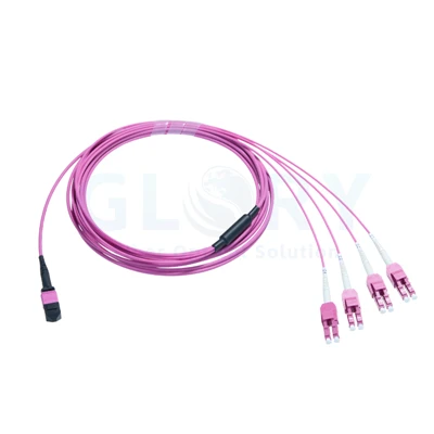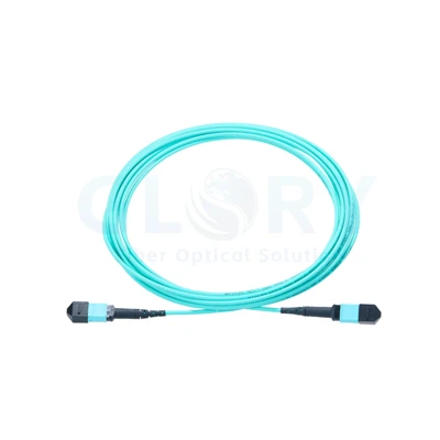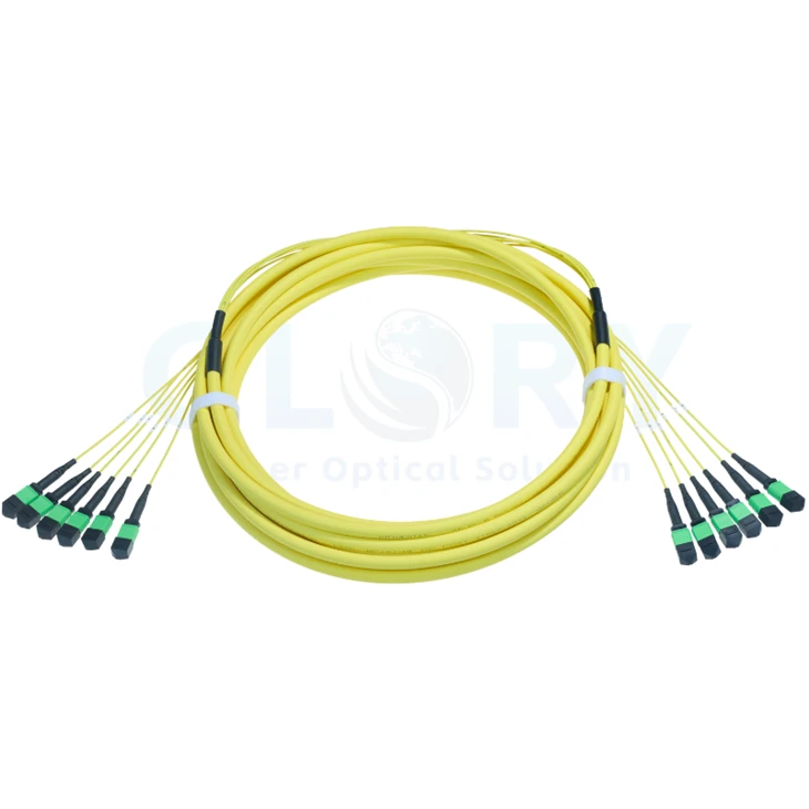
MPO Multi-Connector Trunk Cable
Specify the capacity of a shared OS2 backbone, then divide it into manageable 12-fiber connector groups at each end. Glory Optical's MPO Multi-Connector Trunk Cable is a configurable double-jacket assembly covering 12–576 fibers. Cable length, end genders, polarity, jacket and pulling-eye arrangement are selected around the installation and the mating equipment.
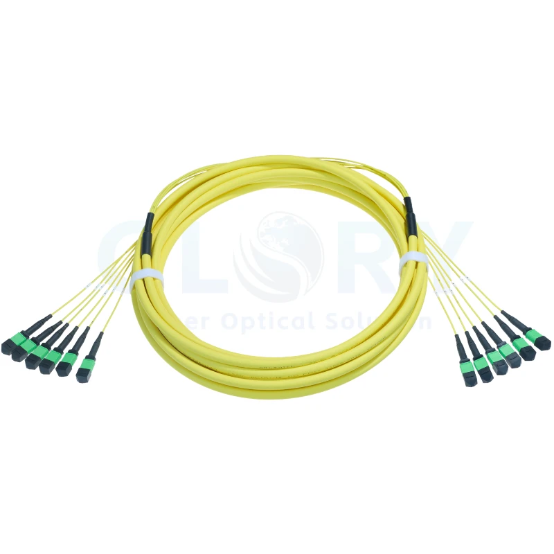
Connector examples for the trunk family. The selected fiber count determines how many 12-fiber connectors are fitted at each end; pictured genders and colors are illustrative. |
Build the Backbone Around Its Required Fiber CapacityOS2 9/125 μm · 12–576 fibers · APC interfaces · Base-12 groups · OFNP or LSZH · configurable end genders Each connector group has its own termination while the cable shares a common trunk route. Define the total fiber requirement first, then match the connector groups to the panels or modules at both destinations. |
Configuration Choices and Published Ratings
| Specification | Selectable configuration or rating |
|---|---|
| Product name | MPO Multi-Connector Trunk Cable |
| Assembly system | Base-12 multi-unit trunk with MPO-compatible connectors at both ends |
| Fiber mode | OS2 single mode, 9/125 μm |
| Fiber-count selections | 12, 24, 36, 48, 72, 96, 144, 192, 216, 288, 432, 576 fibers |
| End A connector choice | US Conec MTP®-12 Elite female or male |
| End B connector choice | US Conec MTP®-12 Elite female or male |
| Optical-face polish | APC at both ends |
| Polarity options | Type A / Type B / Type C |
| Overall length | Project-specified; confirm on the order drawing |
| Jacket options | Plenum (OFNP) / LSZH |
| Cable construction | Double jacket |
| Main cable OD | 3.6–21 mm, dependent on the selected construction |
| Breakout-unit OD | 2.0 mm |
| Breakout length | 0.84 m; confirm measurement references on the drawing |
| Connector insertion loss | ≤0.35 dB maximum; 0.15 dB typical |
| Connector return loss | ≥65 dB |
| Reference wavelengths | 1310 / 1550 nm |
| Attenuation at 1310 nm | ≤0.35 dB/km |
| Attenuation at 1550 nm | ≤0.21 dB/km |
| Glass fiber | G.657.A1 |
| Minimum glass-fiber bend radius | 10 mm |
| Finished-cable bend radius | 10D dynamic / 5D static; D = main cable OD |
| Long-term tensile strength | 100–200 N, configuration-dependent |
| Short-term tensile strength | 300–660 N, configuration-dependent |
| OFNP operating range | −10 to +60°C (14 to 140°F) |
| LSZH operating range | −10 to +70°C (14 to 158°F) |
| OFNP storage range | −10 to +70°C (14 to 158°F) |
| LSZH storage range | −20 to +70°C (−4 to 158°F) |
| Pulling-eye options | None / End A / End B / Both ends |
Cable OD and tensile figures describe a configuration range. The exact values for the ordered fiber count and jacket belong on its approved drawing. Temperature ratings are listed separately for OFNP and LSZH; the completed build should use the ratings for its selected jacket.
Calculate the Number of Connectors at Each End
With 12 populated fibers in each connector group, the number of connectors at one end is the selected fiber count divided by 12. The same total fiber population reaches the other end. Identify every group in the port schedule so the two ends can be traced consistently.
| Total fibers | 12-fiber connectors at End A | 12-fiber connectors at End B |
|---|---|---|
| 12 fibers | 1 connector | 1 connector |
| 24 fibers | 2 connectors | 2 connectors |
| 36 fibers | 3 connectors | 3 connectors |
| 48 fibers | 4 connectors | 4 connectors |
| 72 fibers | 6 connectors | 6 connectors |
| 96 fibers | 8 connectors | 8 connectors |
| 144 fibers | 12 connectors | 12 connectors |
| 192 fibers | 16 connectors | 16 connectors |
| 216 fibers | 18 connectors | 18 connectors |
| 288 fibers | 24 connectors | 24 connectors |
| 432 fibers | 36 connectors | 36 connectors |
| 576 fibers | 48 connectors | 48 connectors |
For example, a 144-fiber trunk has twelve 12-fiber connectors per end; a 576-fiber trunk has forty-eight per end. The 12-fiber choice uses one connector at each end. Agree group numbering, endpoint names and the complete fiber map before the assembly is labeled.
Choose Pin Configuration and Polarity for Both Ends

Mating principle showing the complementary alignment hardware. End A and End B genders are selected for the actual ports in the project. |
Record the Receptacle Details Alongside Every GroupMale connectors carry guide pins; female connectors present the corresponding guide holes. Specify each cable end so every planned connection has the complementary pin arrangement and a compatible APC optical face. End A and End B can be configured separately. A male-to-female, female-to-female or other reviewed arrangement must be selected against the actual panel, cassette or equipment interface, including adapter orientation. Type A, Type B and Type C are available wiring choices for this family. Agree the position map for the complete channel and record it with the group identifiers. Polarity selection needs the downstream modules and equipment routing as well as the trunk itself. |
Connector Components within a Multi-Unit Assembly

General connector construction. The illustration combines alternative gender components and is not a drawing of a specific high-count trunk. |
Maintain Access to Each Connector and Cable ExitEvery 12-fiber unit terminates at a multi-fiber ferrule supported by its internal spring and retention parts. The outer housing provides keying and release features at the corresponding port. A group of connectorized units requires more than the connector footprint alone. Leave room around the release housings, the exit boots and the branch bundle so technicians can identify and service individual ports. Gender hardware follows the approved end configuration. Keep protective caps with unused units, and release a connector by its intended mechanism when changing a circuit. |
| Part of the assembly | Planning requirement |
|---|---|
| Double-jacket main cable | Size the route and supports for the selected main-cable diameter. |
| Breakout transition | Locate the fanout where the specified 0.84 m units can reach their assigned ports. |
| 2.0 mm connectorized units | Organize and label individual 12-fiber groups without crowding the exits. |
| APC connector housings | Match end gender, key orientation and position map to the intended interface. |
| Optional pulling eye | Select its end location and agree the installation attachment and loading method. |
Use a Shared Trunk between Distribution Areas

Distribution-system illustration. Modules and equipment-side connectors are chosen separately from the multi-connector trunk configuration. |
Assign Connector Groups to Modular Distribution HardwareFor cabinet-to-cabinet or zone wiring, map the available trunk groups to the chosen distribution modules. Each module's connector gender, APC interface and internal fiber routing must fit the overall circuit design. Discuss the mounting arrangement through our MPO distribution-panel range. Include the actual module population and port identifiers when reviewing the cable; enclosure space alone does not define its optical connections. Where equipment requires duplex ports, choose appropriate single-mode distribution modules or separate fanout assemblies. The selected downstream components define the duplex pairing of the fibers carried by the trunk. |

Channel concept showing complementary connections. System distance and operating rate depend on the selected optics and the entire installed path. |
Budget the Trunk together with the Other Optical SegmentsChoose compatible single-mode optical equipment for the application. Confirm wavelength, active-fiber use and the interfaces at each connection before calculating the permitted channel loss. The trunk length is selected for the measured route rather than inferred from a generic application image. Add the optical contribution of the fiber and all mated interfaces, modules and additional leads in the proposed path. Use our data center fiber cabling support to review the endpoint schedule, route and passive components as one project. |
Set Out the Route, Fanout and Pulling Arrangement
Measure the main pathway between the two termination areas and reserve room for the connector bundles. The family offers 2, 3, 5, 10, 15, 20, 25 and 30 m preset lengths as well as project length selection. Confirm the measurement convention and final length on the cable drawing.
Select the pulling-eye option for the intended installation direction: none, End A, End B or both ends. Agree how the protective assembly covers the connectorized units and how the cable will be attached during installation. The allowable handling load must follow the specific build and installation method.
Main-cable diameters span 3.6–21 mm across the family. Use the delivered OD when applying the 10D moving and 5D stationary radius requirements. The separate 10 mm glass-fiber rating does not replace the jacketed-cable routing allowance. Keep the branch exits and connector boots supported at the patching area.
Long-term tensile strength ranges from 100 to 200 N and short-term strength from 300 to 660 N according to construction. Request the exact values for the chosen trunk. Double-jacket construction provides additional physical protection, while the planned pathway and supports remain part of the mechanical design.
Match the Jacket to the Project Environment
| Selected jacket | Operating temperature | Storage temperature |
|---|---|---|
| Plenum (OFNP) | −10 to +60°C | −10 to +70°C |
| LSZH | −10 to +70°C | −20 to +70°C |
Specify the jacket required by the installation space and the project's applicable requirements. Include the jacket selection in the part definition and inspection documents so the receiving team can check it together with the fiber count, end genders and labels.
Verify Every Connector Group before Handover
Keep Continuity Results Tied to the End Labels
Trace all populated fibers through the selected routing map, working group by group at the two ends. Record the correspondence between end labels and port numbers. For a higher-count trunk, this group register provides the link between the cable drawing and the individual test paths.
Inspect APC Faces and Apply the Agreed Single-Mode Method
Inspect the connector faces and the counterpart interfaces, clean them when required and check again before mating. Use reference leads suitable for the single-mode APC connection and define the measurement setup and wavelengths in the acceptance procedure.
The stated connector insertion-loss limit is 0.35 dB maximum, with 0.15 dB typical. Minimum return loss is 65 dB. Retain the optical results against the group and fiber identifiers; evaluate the installed channel separately with its complete fiber length and passive connection count.
Coordinate the Trunk with Connected Product Families
| Related range | Detail to align with the trunk |
|---|---|
| MTP/MPO cable assemblies | Base-12 interfaces, OS2 fiber and the selected connector genders. |
| MPO patch panels | Port capacity, cassette mapping and cable-management space. |
| MPO-to-LC fanout assemblies | A separately selected endpoint option; specify OS2 and the required duplex pairing for this trunk. |
Prepare One Configuration Sheet for the Whole Trunk
| Configuration item | Information to send |
|---|---|
| Capacity | Select the total OS2 fiber count and the resulting quantity of 12-fiber connectors per end. |
| Route and length | Measured path, connector access areas, overall length and breakout measurement references. |
| End A / End B | Male or female APC connectors at each end, with the mating-port details. |
| Routing definition | Type A, B or C plus the approved group-to-group and fiber-position drawing. |
| Jacket and installation | OFNP or LSZH, final OD and tensile data, pulling-eye end selection. |
| Identification and supply | Group labels, test records, quantities, packing and delivery requirements. |
Submit the endpoint list and desired capacity to Glory Optical technical sales. The team can review the physical route, connector grouping and documentation before a configuration is released for quotation or sample discussion.
Request a Multi-Connector Trunk Quote View Data Center Cabling Products
MTP® is a registered trademark of US Conec Ltd. Illustrations explain connector and cabling principles; the supplied assembly is defined by the confirmed configuration and drawing.
Glory Optical Connectivity and Project Supply
|
Glory Optical facility in Ningbo, China |
Fiber Products from Our Ningbo OperationOperating since 2008 · Passive optical connectivity · OEM/ODM support Glory Optical serves fiber network projects with passive assemblies, connection components and installation hardware. Our portfolio brings together terminated cables, pigtails, adapters, splitters, fiber boxes and splice closures. Customers include contractors, distributors, operators and equipment businesses purchasing for deployment, maintenance or OEM/ODM supply. Establish the Assembly SpecificationFor a configurable trunk, the reviewed drawing and sample establish the production record. Agree the fiber population, connectors, wiring, construction and identification before release. Manufacturing work across our ranges includes cable termination, component assembly, enclosure production and mold development, with the applicable activities matched to the order. |

A Look at Product Testing
The videos below concern enclosure and closure evaluations. This trunk instead needs the optical and mechanical records specified for its configuration, such as connector inspection, fiber continuity, mapping and loss measurements. Include the required trunk checks in the purchase and acceptance documents.
Water-Spray Evaluation Example |
Sealing Evaluation Example |
Water-Resistance Evaluation Example |
Documentation for Production and Receiving
Make the end-to-end group schedule available to the production and installation teams. Specify any approved drawings, part sheets, label records and applicable test results that must accompany the shipment. State the measurement reference and acceptance scope so each record can be matched to the supplied assembly.
Glory Optical Connectivity and Project Supply | OEM/ODM Assembly Discussion
Send the Trunk Schedule for Review
Share the desired capacity, route length and the interfaces at both destinations. Add jacket, pulling-eye, labeling and document requirements together with quantities and the requested delivery date. Our team can use those details to review the custom build and discuss practical supply arrangements.
Request Supply Pricing | Email Technical Sales
Email: sales@gloryoptic.com
Hot Tags: os2 mpo multi-connector trunk cable, China os2 mpo multi-connector trunk cable manufacturers, suppliers, factory, data center cabling, data center fiber cabling, Mpo 12 Fiber Cable, mtp mpo, Mtp Mpo Fiber, Mtp Mpo Fiber Breakout Cable