A rack-mount and a wall-mount fiber optic enclosure can contain similar adapters, splice trays and cable-management hardware, but they solve different physical-layer problems. Rack-mount units integrate fiber termination into a standardized rack, while wall-mount units create a protected termination or distribution point where installing a rack is unnecessary or impractical.
The correct choice is not simply "rack-mount for large networks and wall-mount for small networks." Start with the network position, then verify three separate capacities-adapter positions, fibers and splices-before checking cable entry, service access, environment and expansion. A high-density enclosure that technicians cannot safely open, clean or reroute is not a high-capacity solution in operational terms.
Rack-Mount vs. Wall-Mount at a Glance
| Selection Factor | Rack-Mount Fiber Enclosure | Wall-Mount Fiber Enclosure |
|---|---|---|
| Primary role | Centralized rack-level termination, patching, splicing or modular cassette integration | Standalone termination, distribution or demarcation at a wall, riser, entrance or remote node |
| Typical locations | Data centers, MDFs, MDA/IDA areas, central equipment rooms and telecom racks | IDFs, telecom rooms, building entrances, FTTB nodes, industrial rooms and protected outdoor walls |
| Mechanical format | Commonly 19-inch, 1U/2U/4U; fixed, sliding or swing-out construction | Direct wall fixing; single-door, dual-door or compartmented construction |
| Capacity tendency | Usually easier to scale across rack units and modular cassettes | Often compact, but high-capacity wall systems also exist; capacity cannot be assumed from mounting style |
| Maintenance pattern | Frequent front patching; internal access depends on drawer, swing-out or cover design | Door-based front access; hinge direction and surrounding wall clearance are critical |
| Cable routing | Integrates with horizontal/vertical rack managers and overhead or underfloor pathways | Often receives riser, entrance or lateral cable directly through top, bottom or side entries |
| Environment | Most common in controlled indoor rooms; project-specific variants may differ | Available for indoor or outdoor use; wall mounting alone does not establish an IP rating |
| Expansion | Add rack units, adapter panels or cassettes within a planned rack architecture | Use spare adapter positions, trays or a larger enclosure; replacement may require wall and cable-route work |
What Is a Rack-Mount Fiber Optic Enclosure?
A rack-mount fiber optic enclosure is a chassis that terminates, protects and organizes optical fibers inside an equipment rack. It may be called a rack-mount fiber patch panel, fiber distribution unit, LIU or rack ODF, depending on region, capacity and function. Names overlap, so the internal configuration matters more than the label.
Most current systems fit a 19-inch rack and occupy one or more rack units. The official IEC 60297-3-100 reference defines basic dimensions for the 482.6 mm (19-inch) series. A purchasing specification should still confirm the mounting bracket, chassis depth, rail position and required front or rear clearance; "19-inch" does not describe every dimension that affects installation.
Typical Components
- Fixed or removable adapter panels for LC, SC, FC, ST or MPO/MTP interfaces;
- splice trays or holders for pigtail fusion splicing;
- spools and guides for patch cords, fanouts and service loops;
- cable clamps, strength-member fixation and strain relief;
- fixed covers, sliding drawers or swing-out trays for service access;
- labels and port maps for moves, adds and changes.
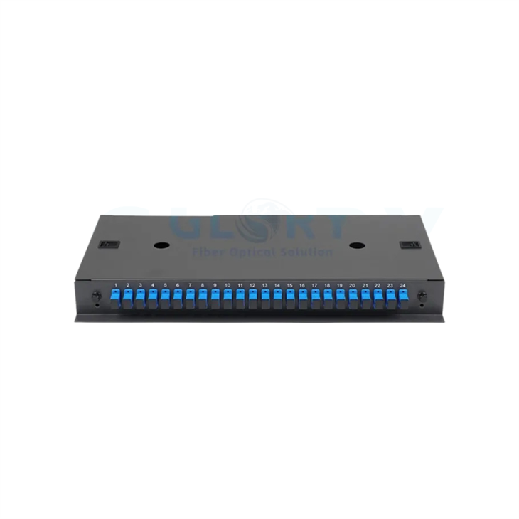
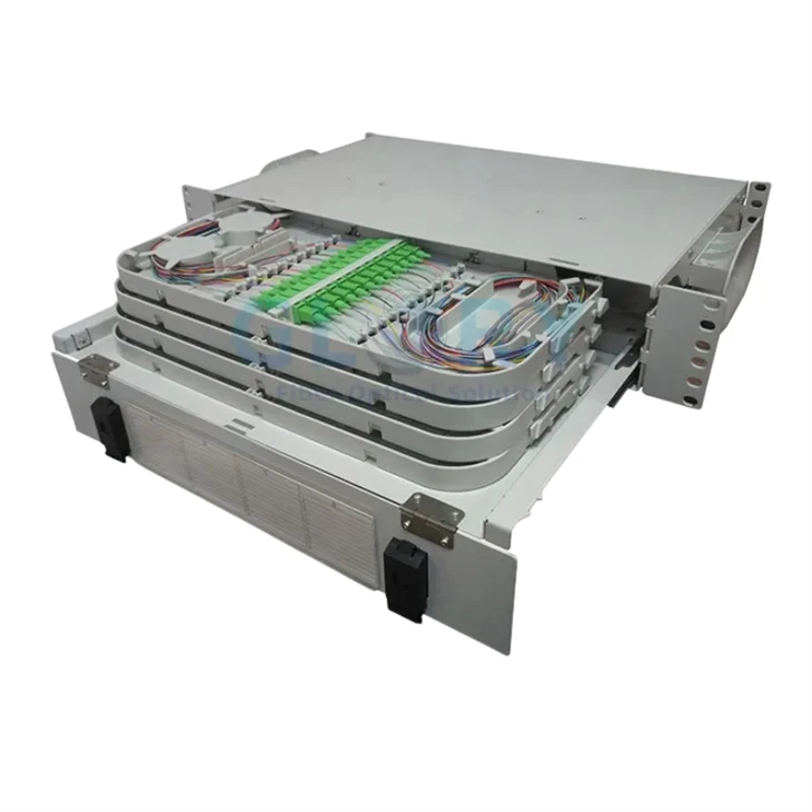
Glory Optical's fiber optic patch panel range includes rack-mount formats for splicing, patching and modular data-center connectivity. For example, the published GL-JPF series is available in 1U and 2U slide-out versions, while the GL-ODF-RS-0248 is a 2U sliding panel with published 48- to 96-fiber configurations.
Best-Fit Applications
Rack mounting is normally the stronger choice when fibers already enter a rack row, patching changes are frequent, active equipment sits nearby, or the network will grow through standardized modules. It also makes labeling and cable-management practices easier to repeat across multiple racks. However, putting every fiber into the smallest possible RU can reduce working space and make cleaning, tracing and splice access slower.
What Is a Wall-Mount Fiber Optic Enclosure?
A wall-mount fiber optic enclosure is fixed directly to a wall, backboard or structural surface. It can provide patching only, splicing only, or an integrated splice-and-patch function. It is often used where the cable enters a building, changes from outside-plant to inside-plant construction, branches toward a floor or tenant, or reaches a small equipment area without a dedicated rack.
A wall enclosure is not automatically a low-capacity product. Commercial systems range from compact two- or eight-fiber boxes to wall cabinets carrying dozens or hundreds of connections. Capacity depends on the adapter system, tray architecture and fiber-management space-not the mounting screws.
Indoor Wall-Mount Enclosures
Indoor versions are common in IDFs, riser rooms, offices, campuses and building entrances. Their selection priorities are usable internal space, door access, cable entry, fiber fixation, labeling and security. A compact indoor 8-core wall-mount termination box, for example, serves a very different role from a rack-level high-density cassette system even though both may contain LC or SC adapters.
Outdoor Wall-Mount Enclosures
Outdoor use is a separate design decision. Confirm the required IP rating, housing material, UV exposure, gasket and gland system, temperature range, lock, mounting hardware and unused-port sealing. The IEC explanation of IP ratings makes clear that IEC 60529 classifies resistance to dust and liquid ingress. "Wall-mount" by itself says nothing about that protection.
For an actual product example, Glory Optical publishes a 24-core IP65 optical distribution box for wall or pole mounting. Its environmental role, cable entries and optional splitter configuration are different from those of an indoor rack panel, even when the nominal fiber count is similar.
Rack-Mount vs. Wall-Mount Fiber Enclosures: The Differences That Affect a Project
Installation Footprint and Mechanical Fit
Rack-mount equipment consumes RU space but uses an existing mechanical framework. Wall-mount equipment preserves rack space but needs a suitable wall, anchors, an unobstructed cable route and room for the door to open. Neither option is "space free." They consume different kinds of space.
For a rack drawer, verify the chassis depth, rail setback, maximum pull-out distance and patch-cord service loop. For a wall box, verify loaded weight, wall substrate, mounting-hole pattern, hinge direction and conflicts with corners, tray work surfaces, pipes or cable containment. Use the product drawing instead of a universal clearance assumption.
Fiber Capacity, Adapter Density and Splice Capacity
These three numbers must be specified independently:
- Adapter capacity describes the number and type of mating interfaces.
- Fiber capacity describes the optical fibers supported by those interfaces or modules.
- Splice capacity describes how many protected fusion or mechanical splices the trays can store.
A "24-port" description is incomplete. It could mean 24 SC simplex adapters and 24 fibers, 24 LC duplex adapters and 48 fibers, or a different modular arrangement. An MPO adapter may pass 8, 12, 16 or 24 fibers, but its useful capacity depends on the cassette, polarity and application. Ask for a port map and internal bill of materials.
Cable Entry, Slack Storage and Bend Management
The enclosure must accept the actual incoming cable, fix its strength member, protect the transition to bare or buffered fibers and store the required slack without tight bends. The Fiber Optic Association's patch-panel routing guidance treats minimum bend radius as a reliability rule, not a cosmetic preference.
A common field mistake is to approve the faceplate and ignore the rear half of the enclosure. The adapters fit, but the feeder cable gland is too small, the armored strength member has no fixation point, or the splice trays occupy the same space needed for service loops. Require an internal layout and cable-entry range before approving the model.
Maintenance Access and MAC Frequency
Rack panels normally support frequent front-side patching and integrate with rack labeling. Sliding or swing-out access can expose internal splices without removing the chassis, but only if the patch cords have enough controlled slack. Wall boxes provide direct front access, but doors and trays can become difficult to use when installed against a corner or above other services.
Ask a practical question: can a technician reach one adapter, clean it, trace the label and open the splice area without disconnecting unrelated live fibers? If the answer is no, nominal density has been purchased at the expense of serviceability.
Environmental Protection, Security and Airflow
Rack-versus-wall is not an optical-performance classification. A passive enclosure does not generate heat, and mounting style alone does not change insertion loss. Loss is affected by connector quality, splices, contamination, alignment and fiber bends.
Enclosures can still influence operations indirectly. Dense patch cords may obstruct neighboring equipment intakes or conceal labels. A public corridor may require a lockable wall box, while a controlled data hall may rely on rack-level access control. Outdoor wall boxes need environmental sealing; indoor rack panels usually prioritize access and density. Treat airflow, access control and ingress protection as separate requirements.
Expansion and Lifecycle Cost
Rack systems usually expand predictably by adding cassettes, adapter panels or rack units. A wall enclosure can also be modular, but replacement may affect cable routing, wall penetrations and service downtime. The lowest first cost is not always the lowest lifecycle cost.
Do not automatically split one high-fiber-count cable across several crowded 1U panels just because each panel reaches an attractive density. Compare that arrangement with a 2U panel that preserves a coherent port map, clearer tray ownership and safer access. Glory Optical's separate guide to drawer-type versus fixed patch panels covers the access mechanism in more detail.
How to Choose Between Rack-Mount and Wall-Mount
Step 1: Locate the Network Function
Mark the enclosure on the network drawing before selecting a product. Is it an equipment-level cross-connect, a backbone termination, a building entrance, a floor distribution point, an operator demarcation or an outdoor access node?
- Inside an established rack row: rack-mount normally fits the workflow.
- At a riser, entrance or distributed room without a rack: wall-mount is often more direct.
- At an outdoor wall or pole: use an enclosure designed for that environment, not an indoor wall box.
- At a large central-office backbone: compare a rack panel with a larger ODF rather than forcing the decision into rack-versus-wall alone.
Step 2: Calculate Three Capacities
Adapter Positions
List the physical interfaces and polish type: LC duplex, SC simplex, MPO/MTP or another approved interface. Do not write only "24 ports."
Fiber Count
Add active fibers, planned dark fibers and approved growth. Then round upward to the available module or tray increment.
Splice Capacity
Count only fibers that will actually be field spliced. Pre-terminated trunk connections may require adapter and slack space without an equal number of splice positions. Conversely, a repair plan may justify keeping a spare tray even when the initial installation is pre-terminated.
Step 3: Confirm the Termination Method
Field-spliced pigtails require splice trays, sleeve holders, work access and protected routing between tray and adapter. Pre-terminated trunks require cable-entry geometry, fanout storage, pulling-eye removal space and compatible modules. A hybrid panel may need both.
Step 4: Draw the Cable Path and Service Envelope
Draw the feeder entry, strength-member clamp, bare-fiber or fanout route, tray position, adapter path and outgoing patch cords. Then draw how the technician opens the enclosure. This simple exercise exposes conflicts that a port-count table cannot show.
Step 5: Match the Environment
Specify indoor or outdoor placement, temperature, dust and water exposure, corrosion risk, public access, wall construction and grounding or bonding requirements where applicable. For wall-mounted outdoor products, confirm the complete sealing system around every used and unused entry-not only the headline IP code.
Step 6: Reserve Growth Without Destroying Serviceability
Growth allowance should be project-specific. Reserve fibers, ports, tray positions and cable-management volume together. Empty adapter positions do not create useful expansion if there is no route for another cable or no space for its service loop.
Capacity Example: Why "48 Ports" Is Not a Complete Specification
Assume a building backbone has 36 active fibers and 12 dark fibers. The installed requirement is already 48 fibers. If the approved growth allowance is 25%, the planning value becomes 60 fibers:
(36 active + 12 dark) × 1.25 = 60 fibers
A 48-position SC simplex panel would be undersized. A 48-position LC duplex panel could present up to 96 fibers, but the enclosure still needs the correct module, splice capacity, incoming-cable fixation and routing space. If the 60 fibers belong to one cable, splitting them across several trays or chassis should preserve a clear port map and cable ownership.
This is why a useful RFQ states the cable count, fiber count, connector format, adapter quantity, splice quantity, growth requirement and port map separately.
Typical Deployment Scenarios
Data Center or MDF
Choose rack-mount when backbone or equipment fibers terminate inside a managed rack environment. Prioritize modular panels, front access, patch-cord routing, labeling and planned RU growth.
IDF or Telecom Room
Use wall-mount when fiber terminates near a riser and the room has no suitable rack. Use rack-mount when active switches and structured managers already occupy a local cabinet.
Building Entrance or FTTB
A wall enclosure can create a clear transition and protect splices close to the cable entry. Verify fire-rated indoor cable transitions, access ownership and the route to the main rack.
Outdoor Access Node
Select a wall- or pole-mount distribution box with the required environmental design, cable glands, splitter space and subscriber-drop arrangement. Do not substitute an indoor patch panel.
Hybrid Network
A common design uses a wall-mount enclosure at the building entrance or floor IDF, then a riser or backbone cable to a rack-mount panel in the MDF or data room. This is not duplication. Each enclosure creates a controlled transition at a different network layer.
Common Selection Mistakes
- Choosing by port count alone. Port terminology changes with SC, LC and MPO/MTP formats.
- Assuming wall-mount means low capacity. High-capacity wall systems exist; compare actual adapter, fiber and splice values.
- Assuming wall-mount means outdoor rated. Mounting and ingress protection are separate attributes.
- Ignoring cable diameter and strength-member fixation. The faceplate may fit while the incoming cable does not.
- Using maximum density as the only target. Leave working room for splicing, cleaning, tracing and service loops.
- Forgetting door or drawer clearance. Confirm the service envelope from the mechanical drawing.
- Mixing adapter capacity with splice capacity. The lower constrained value can determine usable capacity.
- Buying a proprietary module ecosystem without checking availability. Confirm adapter-panel or cassette footprint, polarity and replacement supply.
- Leaving labeling until installation. The port map should be approved with the BOM.
Standards and Documentation to Specify
Mechanical Format and Rack Compatibility
Use the project's applicable rack standard and mechanical drawings. IEC 60297-3-100 is an authoritative reference for the basic 19-inch-series dimensions, but the approved product drawing must still define depth, bracket position, cable entry and operating clearance.
Bend Management and Connector Cleanliness
Follow the cable manufacturer's minimum bend-radius limits and document the internal routing plan. Connector end faces should be inspected under an agreed method. IEC 61300-3-35:2022 addresses the observation and classification of debris, scratches and defects. For a field sequence, see Glory Optical's fiber connector cleaning guide.
Labeling, IP Rating and Quality Documentation
Use the project's administration standard-commonly based on ANSI/TIA-606-D-to define enclosure IDs, cable IDs, ports and records. For an outdoor product, request the applicable IP evidence and confirm cable-entry conditions. For supplier control, ISO 9001 can support confidence in documented manufacturing processes, but it does not certify the performance of every enclosure model. The official ISO 9001 overview describes it as a quality-management-system standard.
How Glory Optical Supports Rack- and Wall-Mount Deployments
Glory Optical supplies passive fiber-management products across data-center, enterprise and FTTx network layers. The purpose of the selection process is not to force every project into one enclosure family; it is to match the mechanical and optical configuration to the actual cable route and maintenance workflow.
Rack-Mount Patch Panels and ODFs
Available rack products include the GL-JPF 1U/2U slide-out patch panel, the GL-ODF-RS-0248 2U sliding patch panel and a 19-inch MPO/LC ODF. The published models cover different fiber counts, tray arrangements and modular interfaces; final configuration should be confirmed against the project BOM.
Wall-Mount Termination and Distribution Boxes
The fiber optic termination box range covers compact indoor wall boxes and outdoor distribution formats. Select by network function and environment rather than treating every wall product as interchangeable.
OEM Configuration and RFQ Documentation
Project configurations may include specified adapters, pigtails, splice trays, module layouts, labels, port maps, cable-entry ranges and packaging. Glory Optical states that its quality management system is ISO 9001 certified; buyers should request the current certificate and applicable scope together with product-level drawings and reports. For custom configuration, use the OEM/ODM fiber support page or send a complete RFQ.
Send the network position, cable schedule, fiber count, adapter format, splice plan, installation environment and expected growth. Glory Optical can compare available rack- and wall-mount configurations against the same project checklist.
View Rack-Mount Panels View Wall-Mount BoxesFinal Recommendation
Choose the mounting method after locating the network function and cable transition. Rack-mount fiber enclosures usually provide the cleanest path for centralized, modular and frequently changed rack environments. Wall-mount enclosures usually provide the cleanest path for distributed termination points, building entrances, risers and sites without a suitable rack.
Then verify what determines whether the enclosure will actually work: adapter format, fiber count, splice capacity, cable entry, strength-member fixation, bend control, service access, environment, labeling and growth. If those fields are missing, "rack-mount" or "wall-mount" is only a housing description-not a complete specification.
Frequently Asked Questions
What is the main difference between a rack-mount and wall-mount fiber enclosure?
A rack-mount enclosure integrates fiber termination and patching into a standardized equipment rack. A wall-mount enclosure creates a standalone termination or distribution point on a vertical surface. The correct choice depends on network position, available infrastructure, capacity, cable route and maintenance workflow.
Does a rack-mount fiber enclosure have lower insertion loss?
No. Mounting style does not determine insertion loss. Optical performance is affected by connectors, adapters, splices, cleanliness, fiber routing and bend control.
Can a wall-mount fiber enclosure support splicing and patching?
Yes. Many wall-mount enclosures include adapter panels, splice trays, cable fixation and slack storage. Specify adapter capacity and splice capacity separately because the two values may not be equal.
Can a wall-mount fiber enclosure be used outdoors?
Only when the specific product is designed and tested for the intended outdoor environment. Wall mounting is an installation method, not an ingress-protection rating. Confirm IP rating, material, cable-entry sealing, UV exposure, temperature range and mounting hardware.
Can rack-mount and wall-mount enclosures be used in the same network?
Yes. A common design uses wall-mount enclosures at building entrances or floor telecom rooms and rack-mount panels in the MDF, MDA or central equipment room.
How much spare capacity should a fiber enclosure have?
There is no universal percentage. Calculate active fibers, dark fibers, approved growth and module increments, then verify that adapter, splice and cable-management capacities all support the plan without making maintenance impractical.
Recommended Glory Fiber Enclosures for This Selection
The following products correspond directly to the rack-mount and wall-mount use cases discussed above. Each card uses a real product image and published product data from the Glory Optical website. Final adapter loading, splice arrangement, cable-entry range and accessories should be confirmed against the project BOM.


Technical scope: Product names and capacities vary by supplier and region. Final project approval should use the applicable datasheet, mechanical drawing, port map, test requirements and local code.