In every fiber optic network, connectors are the smallest components by size yet the largest source of failures by impact. A single dust particle on a 9-micron core, a 1-micron misalignment in a ceramic ferrule, or a mismatched polishing angle can degrade a 400G link from error-free to non-functional. This guide delivers a practical, standards-driven framework for selecting, installing, and maintaining fiber optic connectors across FTTH, data center, and 5G deployments - with a dedicated section on fast field-assembly connectors that are transforming last-mile installation economics.
The Connector Landscape: Types, Standards, and Selection Criteria
Fiber optic connectors come in a dozen form factors, but five families dominate 2026 deployments. Each type is governed by international standards that define interface dimensions, ensuring interoperability across manufacturers. The IEC 61754 series specifies the mechanical interface for each connector family, while the TIA/EIA-604 (FOCIS) series provides the equivalent US standard.
The selection of a connector type is rarely arbitrary - it is dictated by the application, density requirements, environmental conditions, and the prevailing ecosystem in the target market. Understanding the strengths and limitations of each family is the foundation of any cabling specification.
| Connector | Ferrule | Latching | Standard (IEC / TIA) | Primary Applications |
|---|---|---|---|---|
| LC (Lucent) |
1.25mm ceramic | Push-pull latch | IEC 61754-20 / FOCIS-10 | Data centers, enterprise, 5G fronthaul (38.5% market share) |
| SC (Subscriber) | 2.5mm ceramic | Push-pull snap | IEC 61754-4 / FOCIS-3 | FTTH, telecom, PON ONU/OLT |
| FC (Ferrule) |
2.5mm ceramic | Threaded screw-on | IEC 61754-13 / FOCIS-4 | High-vibration, test/measurement, backbone |
| ST (Straight Tip) |
2.5mm ceramic | Bayonet twist-lock | IEC 61754-2 | Legacy, industrial, military (declining) |
| MPO/MTP | MT multi-fiber | Push-pull spring | IEC 61754-7 series | 100G/400G/800G data center parallel optics |
LC: The Data Center Default
The LC connector's 1.25mm ceramic ferrule occupies half the footprint of SC and FC connectors, enabling the high port density required by modern switches and patch panels. Its push-pull latching mechanism provides positive tactile feedback, and the connector is rated for 500+ mating cycles. In 2025, LC connectors held approximately 38.5% of the global single-mode connector market by revenue - roughly $1.02 billion. The LC's dominance in data centers is reinforced by its adoption as the standard duplex interface for 100G LR4, 400G FR4, and 800G LR8 transceivers, and it remains the primary connector for 5G fronthaul CPRI/eCPRI links.
SC: The FTTH Workhorse
The SC connector's 2.5mm ferrule and push-pull snap latching make it the cost-effective choice for FTTH drop cable terminations and PON equipment interfaces. The larger form factor is acceptable in outside-plant cabinets and customer premises where density is not critical. SC connectors are rated for 1000+ mating cycles and are the standard interface on GPON/XGS-PON/50G-PON optical network units (ONUs). The SC/APC variant with its green boot and angled polish is ubiquitous in FTTx deployments worldwide.
MPO/MTP: The Parallel Optics Backbone
For 100G and above, single-fiber connectors give way to multi-fiber MPO/MTP connectors that carry 12, 16, or 24 fibers in a single push-pull housing. The MPO-12 connector, defined in IEC 61754-7-1, supports 40G SR4 and 100G SR4 using 4 TX + 4 RX lanes (8 fibers active). The MPO-16 connector, defined in IEC 61754-7-3, is required for native 800G DR8 with 8 TX + 8 RX lanes. The migration from MPO-12 to MPO-16 is one of the most significant connector transitions in 2026, as hyperscale operators standardize on 800G DR8 infrastructure.
Emerging Small-Form-Factor Connectors
Beyond the five established families, the push toward 400G and 800G density is driving adoption of next-generation small-form-factor (SFF) and very-small-form-factor (VSFF) connectors. The CS connector, the SN connector, and the MDC duplex connector (developed by US Conec) each pack two fibers into a footprint roughly 30% smaller than LC. These connectors are gaining traction in hyperscale data centers where front-panel port density is the limiting factor. However, their market share remains small compared to LC, and ecosystem maturity (cleaning tools, test equipment, trained technicians) lags behind the established families.
2.Polishing Types: UPC vs APC and Why It Matters
The end-face polish of a fiber connector ferrule determines its return loss (RL) performance - the measure of how much light reflects back toward the source. Three polishing types dominate the market: PC (Physical Contact), UPC (Ultra Physical Contact), and APC (Angled Physical Contact). The choice of polish is not interchangeable - it is dictated by the application and must be consistent across a link.
| Polish Type | End-face Geometry | Typical RL | Boot Color (SM) | Application |
|---|---|---|---|---|
| PC | Slightly spherical | ≥ 40 dB | Blue (legacy) | Legacy low-speed links |
| UPC | Extended convex dome | ≥ 50 dB | Blue | Standard SM Ethernet (100G/400G) |
| APC | 8° angled | ≥ 60 dB | Green | FTTx/PON, CATV, DWDM, coherent |
The color coding of connector boots follows an industry convention that enables rapid visual identification: blue for UPC single-mode, green for APC single-mode, aqua for OM3 multimode, magenta for OM4/OM5 multimode, and yellow for single-mode OS2 jacket color. This color system is not just aesthetic - it is the first line of defense against the most dangerous connection error in fiber optics.
Why APC Dominates FTTx
The APC's 8-degree angle causes reflected light to leak into the cladding rather than returning to the laser source, achieving RL of 60 dB or higher (Grade 1 per IEC 61300-3-6). This is critical in PON architectures where reflected light from multiple connectors can accumulate and destabilize the OLT's distributed feedback (DFB) laser. In analog CATV overlay systems carried on the same PON fiber, even small reflections create multipath interference that degrades video signal quality. For these reasons, APC is mandatory in all FTTx/PON deployments, and the SC/APC connector (green boot) is the global standard interface at the ONU.
UPC in Data Center Environments
In data center environments, UPC polish provides adequate return loss (50+ dB) for digital Ethernet links at 10G through 400G. The UPC's flat convex dome (no angle) simplifies manufacturing and enables slightly lower insertion loss than APC - typically 0.1-0.15 dB per mated pair versus 0.15-0.2 dB for APC. However, as data rates push toward 800G and beyond, even UPC's 50 dB RL becomes marginal. At 800G, PAM4 signaling is sensitive to back-reflection that can cause multipath interference and eye-diagram degradation, and some operators are migrating to APC even in data center environments to provide additional margin.
3.MPO/MTP Connectors: High-Density Data Center Connectivity
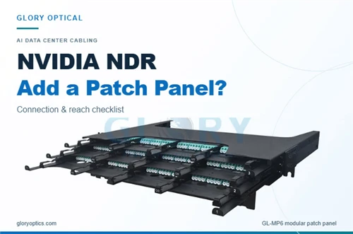
As data center speeds scale from 100G to 400G to 800G, single-fiber LC connectors give way to multi-fiber MPO/MTP connectors that carry 12, 16, or 24 fibers in a single housing. The MPO connector, defined across the IEC 61754-7 series, is the normative array connector for structured cabling per TIA-568 and ISO/IEC 24764. Understanding MPO polarity, male/female configuration, and performance grades is essential for designing and maintaining modern data center fabrics.
MPO-12 vs MPO-16: The 800G Transition
The MPO-12 connector carries 12 fibers in a single row and is the standard interface for 40G SR4 (4+4 lanes) and 100G SR4. For 400G DR4/SR4.2, MPO-12 remains the primary connector with 4 TX and 4 RX lanes using 8 of the 12 fibers. However, 800G DR8 requires 8 TX and 8 RX lanes (16 fibers active), making the MPO-16 connector mandatory for native 800G infrastructure.
MPO-12 and MPO-16 connectors are not interchangeable. They have different fiber pitch patterns (12 fibers at 0.25mm pitch vs 16 fibers at 0.25mm pitch in a wider housing), different alignment pin configurations, and different adapter keying. Migrating from 400G (MPO-12) to 800G (MPO-16) requires new trunk cables, new cassettes, and new adapter plates - a significant infrastructure investment that must be planned in advance.
Polarity Methods: A, B, and C
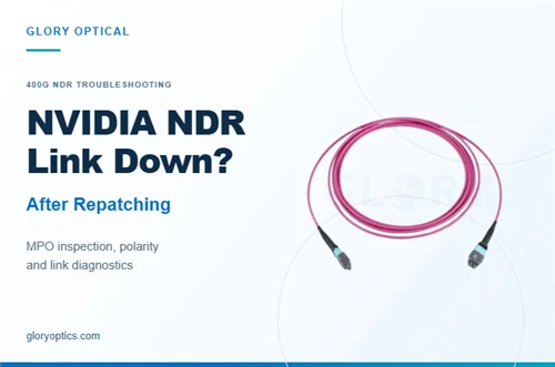
MPO polarity defines how fiber positions are mapped between the TX and RX ends of a link. The TIA-568 standard defines three polarity methods, and choosing the wrong method will cause hard link failures:
| Method | Fiber Mapping | Primary Use Case |
|---|---|---|
| Type A | Straight (1→1), key-up/key-down flip at adapter | Legacy duplex, MPO-to-LC breakout |
| Type B | Reversed (1→12) | De-facto standard: 40G SR4, 100G SR4, 400G DR4 |
| Type C | Adjacent pair flip (1↔2, 3↔4...) | Required for 800G DR8 (TX on odd, RX on even) |
4.Field Assembly Connectors: Fast Termination for FTTH and 5G
Not every fiber termination happens in a factory with diamond-polishing equipment. In FTTH last-mile deployment, 5G cell site installation, and emergency field repairs, technicians must terminate fiber on-site, often in challenging environmental conditions. Field assembly connectors - also called fast connectors, quick connectors, or mechanical splice connectors - eliminate the need for epoxy, polishing, and fusion splicers, enabling terminations in under two minutes with simple hand tools.
Three Field Termination Methods Compared
| Method | Time/Termination | Typical IL | Typical RL | Equipment Cost |
|---|---|---|---|---|
| Fast (mechanical splice) | < 60 sec - 2 min | ≤ 0.3 dB | ≥ 45 dB (UPC) / ≥ 50 dB (APC) | Low (cleaver + stripper) |
| Fusion splice-on connector | 3-8 min | ≤ 0.1 dB | ≥ 60 dB | High ($500-$5,000+ splicer) |
| Epoxy/polish (traditional) | 20-30 min | 0.2-0.3 dB | Varies | Moderate (oven, polishing jig) |
Fast connectors use a pre-polished ceramic ferrule inside the connector body. The field technician strips the cable jacket, cleans the bare fiber, cleaves it with a precision cleaver, and inserts the cleaved fiber into the connector where it butts against the pre-polished end-face. A V-groove mechanical clamping mechanism locks the fiber in position, creating a mechanical splice between the field fiber and the factory-polished stub.
Anatomy of a Quick-Assembly Connector
To illustrate how field assembly connectors work in practice, let's examine a representative product - the LX01-B SC Gear Quick Assembly Connector - whose specification sheet provides detailed insight into the mechanical design and installation process.

LX01-B SC Gear Quick Assembly Connector.
| Parameter | Specification |
|---|---|
| Product Model | LX01-B SC Gear Quick Assembly Connector |
| Ferrule Type | SC, 2.5mm ceramic (pre-polished) |
| Polishing Types | SM/UPC (blue) and SM/APC (green) |
| Fiber Compatibility | 125µm cladding diameter (SM fiber) |
| Cable Compatibility | Drop cable 2.0×3.0mm / 2.0×5.0mm; Round cable Ø5.0/3.0/2.0/0.9mm |
| Insertion Loss (avg) | ≤ 0.3 dB |
| Insertion Loss (max) | ≤ 0.5 dB |
| Return Loss (UPC) | ≥ 50 dB |
| Return Loss (APC) | ≥ 55 dB |
| Operating Temperature | -20°C to +75°C |
| Mating Durability | 500 cycles minimum |
| Tensile Strength | ≥ 50N |
| Overall Length | 60mm |
Installation Steps: 12-Step Visual Guide
The LX01-B specification sheet defines a precise 12-step installation procedure that a trained technician can complete in under two minutes. Each step below includes a photograph from the official product documentation, showing the exact hand positioning and tool usage required

Official 12-step quick assembly SC connector operation guide.
Critical Installation Notes
Steps 2 through 4 must be performed in exact sequence – the screw cap must be threaded onto the cable before stripping, and the fixed length device ensures consistent fiber exposure. The slight fiber bend maintained in Step 8 is essential: it creates spring-loaded contact pressure within the V-groove, maintaining physical contact between the cleaved fiber end-face and the pre-polished ferrule. Skipping or rushing the cleaning step (Step 6) is the most common cause of elevated insertion loss in field-assembled connectors.
Why Fast Connectors Win in FTTH
For FTTH last-mile deployment, fast connectors offer three decisive advantages over fusion splicing. First, no capital equipment - no $5,000 fusion splicer is needed, just a $50 cleaver and $30 stripper. Second, speed - a trained technician terminates a connector in under 2 minutes versus 5-8 minutes for fusion, enabling 200+ terminations per day. Third, re-terminability - if a termination fails testing, the connector can be opened, re-cleaved, and re-terminated without discarding it. Fusion splice-on connectors, by contrast, are permanent once spliced. Most operators use fast connectors for the drop cable (subscriber side) and fusion for the feeder cable (central office side), combining the speed of mechanical splicing with the performance of fusion where each matters most.
Fast Connector Applications Beyond FTTH
While FTTH is the largest market for fast connectors, the technology is increasingly adopted in two other segments. In 5G FTTA deployment, fast connectors enable rapid cell site activation - a crew of two technicians can terminate all fronthaul fibers at a base station in under an hour, compared to half a day with fusion splicing. The LX01-B's -20°C to +75°C operating range and IP65+ environmental rating make it suitable for outdoor cabinet and tower-top installations.
In emergency repair scenarios, fast connectors provide a rapid restoration path for damaged cables. A technician can cut out a damaged section, strip and cleave both ends, and install fast connectors in under 5 minutes per end - restoring service while a permanent fusion splice repair is scheduled. The mechanical splice's IL of 0.3 dB is acceptable for temporary restoration, and the connector can remain in service indefinitely if the link budget allows.
5.Installation Tools and Best Practices
Successful fiber connector installation requires the right tools, used in the correct sequence, with rigorous quality verification. A well-equipped field installation kit enables a technician to strip, cleave, splice/terminate, clean, inspect, and test fiber connections with consistent quality. The investment in proper tools pays for itself many times over by eliminating rework and field failures.
The Cleave Quality Imperative
For both fast connectors and fusion splicing, cleave quality is the single most important determinant of termination performance. A precision cleaver produces a clean, flat (or nearly flat) break with a cleave angle under 0.5 degrees. This clean end-face is what allows the fiber to butt against the pre-polished stub in a fast connector or fuse seamlessly in a fusion splice. A bad cleave - with a chip, hackle, or angle exceeding 1 degree - creates a gap or misalignment that directly increases insertion loss and can cause the termination to fail entirely.
The cost difference between precision and economy cleavers is modest ($200-400 for precision vs $50-100 for economy), but the performance difference is significant. Economy cleavers produce acceptable results for multimode and low-speed single-mode but may produce inconsistent angles that cause marginal performance in high-speed single-mode applications. For any deployment involving 10G+ single-mode, a precision cleaver is non-negotiable.
Testing and Certification Workflow
Post-installation testing follows a tiered approach. The first tier is continuity testing using a VFL - a quick pass/fail check that verifies the fiber path is continuous and identifies gross faults. The second tier is insertion loss testing using an OLTS (optical loss test set), which measures the end-to-end loss of the link against the design budget. The third tier is OTDR testing, which provides a distance-resolved profile of the link, showing the location and magnitude of every splice, connector, and bend along the route.
For data center deployments, the certification standard is increasingly stringent. An 800G DR8 link with four MPO patch points and 500 meters of fiber must achieve total IL ≤ 4.0 dB. The OTDR trace should show each connector pair at ≤ 0.35 dB, each fusion splice at ≤ 0.1 dB, and fiber attenuation at ≤ 0.35 dB/km. Any connector exceeding 0.5 dB must be cleaned, re-inspected, and re-tested; if it still fails, the connector or trunk must be replaced.
Market Segmentation by Application
The connector market is segmented by application into three roughly equal thirds. FTTH/broadband represents the largest segment at approximately 30%+ of demand, driven by national broadband plans in China, India, and Southeast Asia, and European Digital Decade targets. The global FTTx market reached $28.6 billion in 2025 and is projected to nearly double to $58.4 billion by 2034 at a CAGR of 8.2%, with FTTx passive connectivity (connectors, splitters, closures) at $5.45 billion growing to $10.06 billion by 2032.
The 5G transport segment accounts for approximately 25% of connector demand, driven by fiber-fed cell sites requiring LC duplex connectors for CPRI/eCPRI fronthaul and ruggedized outdoor connectors for tower-top electronics. The data center segment, while currently smaller at approximately 20% of connector volume, is the fastest-growing as MPO/MTP connector adoption accelerates with 400G and 800G deployments.
Regional Dynamics
Asia Pacific leads regional connector demand, driven by China's massive 5G and FTTH buildout (estimated 180-220 million new drop cable units installed in 2025), Japan's FTTH saturation, and India's BharatNet rural connectivity project. North America follows, with hyperscale data center construction (particularly in Northern Virginia, Dallas, and Phoenix) as the primary growth driver. Europe accounts for steady growth, with Spain, France, and Germany accelerating FTTH deployment to meet Digital Decade targets of 450 million homes passed by 2030.
Competitive Landscape
The global fiber optic connector market is moderately fragmented, with the top six public companies holding approximately 46% of combined market share. Corning Incorporated (USA) leads with approximately 18-22% global share, strengthened by strategic cloud-provider partnerships and a broad portfolio spanning MTP/MPO, MDC duplex, and MMC multi-fiber connectors. Other major players include CommScope (USA), Amphenol (USA), Molex (USA), Sumitomo Electric (Japan), FIT/Furukawa Electric, US Conec (USA, developer of ELiMENT MDC and MMC VSFF connectors), and Senko (Japan, major LC/MPO manufacturer).
Technology Trends Shaping 2026 and Beyond
Three technology trends are reshaping the connector landscape. First, small-form-factor (SFF/VSFF) connectors - CS, SN, MDC - are gaining traction as hyperscale operators seek to maximize front-panel port density for 400G+ transceivers. Second, MPO-16 adoption is accelerating as 800G DR8 moves from early adoption to mainstream deployment, requiring new trunk cables, cassettes, and polarity management. Third, field-terminable connector technology continues to improve, with mechanical splice IL approaching 0.1 dB in the latest designs - narrowing the performance gap with fusion splice-on connectors and expanding the addressable application range.
Looking further ahead, co-packaged optics (CPO) represents the most disruptive trend on the horizon. By integrating optical transceivers directly with switch ASICs, CPO eliminates front-panel connectors entirely for the highest-bandwidth ports. While CPO is not expected to reach volume production before 2028, its potential to reduce the connector count in hyperscale data centers by 50% or more is already influencing long-term infrastructure planning.
Conclusion: The Practical Selection Framework
Connector selection is not a single decision but a series of decisions that cascade through the network architecture: connector type, polish type, ferrule grade, polarity method, and termination method. Each decision must be aligned with the application, performance requirements, and lifecycle expectations. The framework below synthesizes the technical, economic, and operational factors discussed throughout this guide into actionable guidance.
- FTTH/PON last-mile: SC/APC fast connectors (e.g., LX01-B SC Gear) for drop cable termination. The 2-minute installation time, no-equipment requirement, and re-terminability make fast connectors the optimal choice for subscriber-side termination. Use fusion splice-on connectors for the feeder side at the OLT.
- Data center access layer (GPU-to-leaf, <30m): LC/UPC duplex with premium ferrules (≤ 0.7µm concentricity) or MPO-12 Type B for 100G/400G parallel optics. Low-loss (≤ 0.35 dB) MPO-12 for 400G DR4/SR4.
- Data center spine/DCI (100m-10km): LC/UPC duplex for 100G/400G/800G LR/ER transceivers. OS2 single-mode with Grade B connectors (≤ 0.25 dB IL). Migrate to APC for 800G+ if link budget requires.
- 800G data center (DR8): MPO-16 Type C polarity, low-loss (≤ 0.35 dB) elite grade, female connectors on trunks. Polarity audit mandatory before cutover.
- 5G fronthaul (CPRI/eCPRI): LC/UPC duplex single-mode for BBU-to-RRU links. Outdoor-rated connectors with IP65+ sealing for tower-top installations. OS2 G.652D fiber.
- 5G backhaul/midhaul: LC/UPC duplex single-mode, SC/UPC at distribution frames. Fusion splice for permanent joints, fast connectors for emergency repair.
- High-vibration environments: FC threaded connectors with strain-relief boots. The screw-on coupling provides superior mechanical stability versus push-pull latching.
- Legacy multimode (OM3/OM4): LC/UPC duplex, beige/aqua boots. Do not mix polish types - all multimode should be UPC. Upgrade to OM5 + SWDM4 if extending the life of existing multimode plant.
The organizations that deploy fiber most successfully are those that treat connectors not as commodity components but as precision instruments requiring careful specification, proper installation, and rigorous maintenance. A $5 connector can compromise a $50,000 transceiver link if its ferrule is contaminated, its polish is mismatched, or its polarity is wrong. Investing in connector quality, technician training, and cleaning discipline pays dividends across the entire 15-20 year lifecycle of the fiber plant.