An FC connector can feel firmly attached while its optical performance changes each time it is reconnected. The coupling nut may be tight, yet a contaminated end face, an unsuitable keyway or a cable pulling against the boot can still make the connection unreliable. The useful question is what the complete assembly does after installation and during the next maintenance visit.
A secure FC connection starts with the correct mating interface. It then needs a stable panel mounting, a clean optical contact and measurements that can be repeated under a defined test method. Keeping records of those conditions makes a later fault much easier to diagnose.
What security means for an FC adapter
Here, security covers mechanical retention, stable optical transmission, protection from the service environment and control of physical access. A standard FC mating adapter is a passive alignment component. It has no firmware to patch and does not encrypt the traffic passing through it. Encryption and network access policies belong to the equipment and systems around the optical link.
The distinction matters when specifying a part. A threaded coupling addresses connector retention. An alignment sleeve positions the ferrules. A cabinet lock limits access. Each solves a different problem, and one cannot stand in for another.
Optical transmission is also insensitive to electromagnetic pickup. Electrical compatibility and grounding still matter for nearby equipment and conductive cable parts. At the passive optical mating point, focus protection on contamination, alignment and mechanical stress.
Where this guide applies
FC interfaces remain relevant on optical instruments, existing distribution frames and equipment built around screw coupled connectors. HUBER+SUHNER identifies legacy products and test and measurement as applications for its FC adapter range. An installed FC system therefore deserves careful maintenance even when a new project uses another connector family.
The following sections examine the decisions a buyer or technician can actually verify: interface compatibility, installation, cleaning, environmental protection, optical acceptance and fault isolation. They also explain what to request from a supplier before approving a batch. The scope is conventional passive FC mating adapters for physical contact connections; specialized free space, high power and vacuum interfaces require their own procedures.
How an FC connection stays aligned
In a conventional FC to FC mating adapter, the fibers are held in ferrules in the two plugs. The adapter guides those ferrules into an alignment sleeve so that the fiber ends can meet. The ordinary adapter does not contain a length of transmission fiber. Its housing and sleeve establish the mechanical conditions for the optical contact.

FC uses a screw on coupling and a nominal 2.5 mm ferrule. The connector key limits rotation, while the connector mechanism maintains contact when properly assembled. The panel fastener secures the adapter body to the panel. Tightening the connector nut cannot repair a loose panel mounting.
These distinctions help explain an intermittent port. A body that moves in the panel suggests a mounting problem. A result that changes after reconnecting suggests checking cleanliness, key fit, the sleeve and the reference leads. Neither observation proves which part has failed, but both narrow the investigation.
Specify the mating interface before ordering
An order line that says only "FC adapter" leaves several important choices open. A replacement may fit the panel and accept the connector nut while still providing the wrong keyway, an unsuitable mounting arrangement or an unapproved optical pairing. Start with the connector part numbers on both sides, including the pigtail hidden behind the panel.
Polish belongs to the connector end face
PC and UPC describe physical contact polishing arrangements; APC uses an angled physical contact surface, commonly at 8 degrees. The adapter itself has no polished fiber end in an ordinary mating sleeve design. An "APC adapter" designation identifies the intended mating arrangement, including its mechanical compatibility, rather than a polishing process applied to the adapter.
|
Item to confirm |
What the purchase record should establish |
|---|---|
|
Polish on both plugs |
Identify PC, UPC or APC from approved part numbers. Keep an APC mating path APC compatible. |
|
Key and keyway |
Specify the dimensional variant and orientation. Require a supplier drawing where the description is ambiguous. |
|
Fiber and test conditions |
State single mode or multimode, the fiber family, wavelengths and the intended reference connectors. |
|
Sleeve and construction |
Record the specified sleeve material, body style and any serviceable parts. |
|
Panel integration |
Confirm cutout, panel thickness, flange or nut arrangement, washer stack and access for fingers or tools. |
APC should not be mated directly to a PC or UPC connector. Their end face geometry differs, creating the possibility of poor contact and damage. PC and UPC pairings also need to meet the specified optical performance; a connector that physically fits is not evidence that a mixed pairing satisfies the intended return loss grade.
Use drawings to resolve ambiguous names
IEC 61754-13:2024 covers the FC-PC connector family interface dimensions and includes an intermateability section. Its corrected version incorporates a June 2025 corrigendum. An interface standard reference is useful, but the RFQ should still identify the particular configuration and drawing revision. It does not by itself prove the environmental or optical performance of the purchased assembly.
Color can help technicians identify inventory, but it should not carry the entire compatibility decision. Dust caps are removable, metal bodies may be uncolored and older installations can contain replacements from several suppliers. Label the port and retain the connector part numbers in the maintenance record.
The FC APC keying problem
FC keying deserves its own check because a threaded connection can conceal rotational play. Thorlabs explains that a narrow key can enter a wider slot and rotate slightly. It recommends a matching narrow slot for its narrow key FC/APC cables to preserve alignment. A wide key does not fit its narrow slot.

For an APC replacement, a useful approval exercise is to reconnect the intended cord several times using the same installation procedure and record the optical results. Unexplained scatter is a reason to investigate the pairing before buying a larger batch. This is a project screening exercise, separate from a formal durability qualification.
Install the adapter and support the cable
Treat panel installation and connector mating as separate operations. The first establishes a stable port. The second brings the optical surfaces together. A technician should be able to connect and disconnect a cord without turning the adapter body, twisting the cable or disturbing the pigtail behind the panel.
Establish the port before mating the cord
Check the cutout against the approved drawing and remove burrs that could prevent the flange or washer from seating. Confirm that the panel thickness suits the fixing arrangement. Fit the specified mounting hardware and orientation features, then secure the adapter using the manufacturer's instructions. Keep the optical openings protected while this work is performed.
Where the mounting arrangement allows the body to rotate, hold it as directed while securing the panel hardware. Confirm the rear pigtail remains relaxed. A port can look correct from the front while its rear cable has been wound around the fixing nut or pressed against an adjacent bracket.
Make the optical connection in a controlled sequence
- Confirm the connector and adapter identities before removing caps. Check the keyway and threads for visible damage.
- Establish safe working conditions, inspect both mating end faces and clean only as needed using an approved process.
- Align the key with the slot. Introduce the connector on the adapter axis without using the coupling nut to force an uncertain fit.
- Rotate the coupling nut while keeping the connector body and cable from twisting. If it binds or will not seat normally, withdraw and investigate.
- Finish according to the connector manufacturer's method. Apply a numeric torque only when it is specified for that exact connector or assembly.
- Support the cord, arrange slack and check access to adjacent ports. Recheck optical performance after the final route is in place.
Stop mating if threads bind, a ferrule is chipped or debris keeps appearing. Segregate suspect parts to protect reference cords and prevent accidental reuse.
There is no safe universal instruction to tighten every FC connector with pliers, add an extra turn or use one torque value across all products. The panel nut and connector coupling nut may also have different requirements. A purchasing specification should keep those instructions distinct.
Clean the optical surfaces without adding damage
An adapter can transfer contamination between two otherwise serviceable cords. A clean patch cord does not remain clean after it touches a dirty rear pigtail. Inspect both mating surfaces, including the end behind the bulkhead, using a probe and tip suitable for the FC interface and polish. A clean front opening says little about the hidden contact.
Inspect before deciding to clean
Set the inspection instrument to the appropriate fiber and connector criteria. Review focus and image quality before accepting an automated result. Dust caps reduce exposure during handling and storage, but a cap is not proof that a connector is clean. Inspect after uncapping and before mating.
Use a cleaner intended for the 2.5 mm ferrule and the particular accessible or recessed interface. Follow the tool manufacturer's stroke, engagement and material guidance. Reusing an exposed wipe area or pressing a dirty tool into the port can move contamination rather than remove it.
If the approved procedure calls for a solvent step, use the specified optical grade product and a controlled wet to dry technique. Allow the surface to finish dry before reconnection. Flooding the adapter can carry residue into the sleeve or leave liquid where it is difficult to inspect. Household tissues, oily workshop air and improvised cleaning sticks give poor control over that risk.
Separate contamination from permanent damage
Loose debris may move or disappear after cleaning. A scratch or embedded defect can remain. Save the image, apply the agreed assessment process and investigate persistent contamination instead of running an endless cleaning cycle. A scratched or chipped ferrule may require replacement, while the acceptance decision for a fixed visual defect also depends on the optical evidence and project rules.
Avoid unnecessary disturbance
A stable, protected connection does not need to be disconnected simply because a calendar reminder says "clean." Plan inspection around installation, reconnection, exposure and symptoms. When a port has been opened during maintenance, inspect the mating ends again and record the subsequent optical check.
A repeated need to clean the same location should trigger a review of the cabinet, caps, tools and work area. Replacing a dirty connector without changing the source of contamination can produce the same fault at the next visit. Cleaning records become more useful when they include where the debris was found and whether it returned.
Keep inspection and optical acceptance together
The inspection image, the insertion loss reading and any required return loss result answer different questions. A clean looking end face establishes neither the loss nor the reflection of the installed mating pair. Build the work instruction so that the technician can complete all the required checks without guessing what counts as acceptance.

If a cleaned connector retains a fixed defect, keep the image and use the project's escalation and optical acceptance procedure. The resulting record should show what was observed, what was measured and why the connection was released or replaced. An unexplained "pass" provides little help when the port is reopened later.
Qualify parts for the actual service conditions
A bench test establishes the condition of the sample at that moment. A connection used near machinery, in a frequently opened cabinet or in an unconditioned shelter faces other stresses. Qualification should represent the intended assembly and exposure, with clear optical acceptance criteria before, during where required and after the test.
|
Service concern |
Relevant test reference |
What the purchaser still needs to define |
|---|---|---|
|
Frequent reconnection |
IEC 61300-2-2:2026 mating durability |
Applicable severity, cleaning conditions, connector pairing and allowed degradation. |
|
Vibration in service |
IEC 61300-2-1:2023 sinusoidal vibration |
Mounting, cable loading, test conditions and optical monitoring. |
|
Changing temperature |
IEC 61300-2-22:2024 change of temperature |
Temperature extremes, transitions, cycles and required performance. |
|
Fiber or cable attachment |
IEC 61300-2-4 fiber or cable retention |
Applicability to the cord or assembly, load conditions and acceptance. |
The retention test reference concerns fiber or cable attachment. It should not be presented as proof of every connector coupling or panel fixing claim. Likewise, an FC thread may help retain a plug but does not establish that an unspecified assembly passes vibration testing. The evidence must identify what was tested and how it was mounted.
Read a durability claim with its conditions
IEC published the 2026 edition of the mating durability method on 14 July 2026. It evaluates successive mating cycles and their effects on optical performance and mechanical degradation. Agree the applicable edition in the purchase documents. An older report can still contain useful evidence, but its method and severity need to be reviewed against the project requirement.
A statement such as "1,000 mating cycles" is incomplete without the test conditions and allowed change. It does not translate directly into a guaranteed number of maintenance years. Cycle counts also need to be read alongside the maintenance and cleaning procedure used during the test.
Make incoming inspection proportionate
For routine receiving, verify the ordered variant, caps, packaging, threads, keyway and panel fit. Use an agreed optical sampling plan and preserve lot identity. Before volume approval of a new design or supplier, test representative production parts with the cords and panel configuration that will actually be used.
A small workshop reconnect exercise can expose an obvious mismatch or unstable pairing. It does not establish a population failure rate. Specify sample size, selection and allowable failures according to the project's risk and purchasing plan, and keep qualification evidence separate from routine receiving records.
A purchasing specification that installers can use
Write the RFQ around the complete connection. A supplier can respond much more precisely to connector part numbers, a panel drawing and a test requirement than to a request for a "high security FC adapter." The documents should let receiving staff, installers and maintenance technicians identify the same approved configuration.
Information to put in the RFQ
- Identify the two mating connector part numbers, their polish and fiber type. State any polarization maintaining requirement explicitly.
- Specify the key and keyway variant, orientation requirement and relevant interface standard. Attach the mechanical drawing or request approval of a supplier drawing.
- Define the body style, sleeve material, panel cutout, panel thickness and mounting hardware. Include the space available behind the panel.
- Set the insertion loss requirement with wavelengths, reference method, connector population and treatment of uncertainty. State whether the claim is a maximum or a statistical value.
- Add the return loss or reflection requirement where the application needs it, with the measurement boundary and method.
- Define the service environment and any qualification evidence required. State the test editions, severities and allowable optical change.
- Request the connector mating instructions separately from panel fixing instructions, including any specified torque for the exact parts.
- Specify packaging, protective caps, lot identification, traceability and the receiving inspection plan.
For example, "insertion loss no greater than the agreed limit for the defined mating pair at the specified wavelengths" becomes enforceable only when the limit and setup are actually supplied. Leaving either blank invites each party to use a different interpretation. The same applies to a durability number without a permitted change in performance.
Keep a short release record for each installed port
Record the cabinet and port ID, adapter variant and lot, cord IDs, test date and technician. Include the optical reference method, wavelengths, instrument identity and results against the approved limits. Retain inspection images when required, and photograph the final cable route where routing was part of the problem.
This record connects a future symptom to the installed configuration. It also makes a supplier discussion more useful: the relevant question becomes whether the approved assembly changed, rather than whether an unnamed FC adapter is "good."
 |
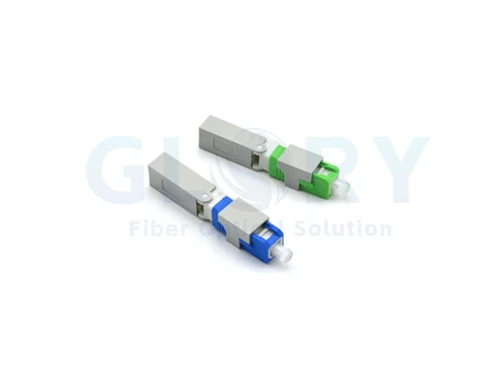
FC AdapterWhen discussing an FC supply requirement with Glory Optical, send the two connector specifications and the panel drawing with the RFQ. The FC adapter product page is a useful starting point for the product family; the approved variant and project test requirements should control the final order. |