Rural broadband · FTTH ODN · Procurement guide
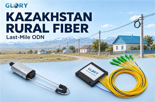
On 4 November 2026, Kazakhstan's digital ministry announced a cooperation arrangement covering more than 1,000 villages. Local small and medium operators can use Kazakhtelecom's existing trunk lines and build GPON last-mile networks, with a stated target of at least 100 Mbps (ministry announcement, in Kazakh). The announcement matters because it speaks to a question the national plan leaves open. Once a trunk fiber reaches a village, who builds the network that reaches the houses?
That work is the village-level optical distribution network (ODN): a splitter point, distribution and drop cable, and an ONT in each home. For an operator or contractor it turns into a bill of materials, and a BOM only holds together when route, cable and optical-budget inputs are known. This guide follows the path from the national plan down to those inputs, then looks at two component groups where mismatches are common: aerial cable hardware and PLC splitters. Recommendations here are engineering reasoning. They do not describe what any Kazakh project has specified.
- A village plan, a village backbone and a connected home are three different delivery stages.
- Aerial hardware is chosen against the actual cable construction and route loads. PLC splitters are chosen against the optical budget, the interface and the enclosure.
- An RFQ becomes usable when it carries route data and asks the supplier for matching and test evidence.
What Kazakhstan's 3,000+ Village Plan Covers
In June 2025 the ministry published an investment agreement for more than 3,000 rural settlements, backed by over 239 billion tenge of extra-budgetary investment. The plan combines fiber and satellite connections, sets two year-end milestones (2026 and 2027), and includes fiber links to mobile base stations as well as to villages.
The programme sits inside a wider national goal. A government statement of October 2025 aims at internet access for the whole population by 2027. Population coverage and village coverage use different denominators, so their percentages do not move together and should not be treated as one KPI.
Two cautions help when reading the headline numbers. The fiber/satellite mix, reported as roughly 88% and 12%, describes planned connection methods and says nothing about how many homes have FTTH today. A fiber line to a base station also does not show that a household network follows the same route. At the time of writing no acceptance announcement for the national fiber build was found, so every figure below is read as a plan, a target or a dated progress report.
- 22 Feb 2024Financing
World Bank approves US$92.43 million for the DARE project, which supports backhaul and last-mile construction in selected underserved areas through competitive matching grants (World Bank). - 9 Jun 2025Target
Investment agreement for 3,000+ rural settlements and 239 billion+ tenge of extra-budgetary investment. - 21 Oct 2025Target
Government goal of internet access for the whole population by 2027. - 20 Aug 2026Progress report
As of that date, 12 villages under the agreement had been brought onto fiber and 340 onto satellite. A separate last-mile subsidy project covers 1,123 villages (Prime Minister's office). - 4 Nov 2026Cooperation announcement
Local operators can use existing trunk lines for GPON last-mile networks across 1,000+ villages.
Milestones as announced. Targets, dated progress reports and cooperation announcements are different kinds of statement and are labelled separately. The 20 August figures are not a November completion count.
How the Last Mile Is Moving Beyond Village Backhaul
Village backhaul brings capacity to the edge of a settlement. Household service needs three more elements: an access node (OLT), a passive ODN inside the village, and a drop to each building. The 4 November announcement is aimed at that second stage. It lets local operators use existing trunk lines instead of building their own, with GPON as the stated last-mile technology. The announcement dates those trunk lines to a build period of 2018–2020.
Funding routes approach the same gap from different directions. The August 2026 national-projects statement lists, next to the main agreement, a separate last-mile subsidy project of 83.9 billion tenge covering 1,123 villages. The World Bank's DARE financing, approved in 2024, supports selected backhaul and last-mile projects through competitive matching grants.
These numbers overlap in purpose but not necessarily in scope. The 3,000+, 1,123 and 1,000+ village figures come from three different announcements, and no village-by-village list tying them together was found. They should not be added together, and tenge amounts should not be summed with the dollar financing. For a supplier or contractor the practical consequence is that the buyer is often a local operator, or its EPC contractor, working on a village-scale package. The first documents that buyer needs are route, cable and optical-budget inputs. For a configured view of village ODN components, see Glory's FTTH ODN project configuration.
Map the Route Before Choosing ODN Components
Village access splits into stages with different owners and different parts. Regional transmission and village backhaul end at a handoff point. The OLT sits where the operator's design places it. One or more splitter points divide each PON port. Distribution and drop cable then runs to each building, where the ONT terminates the service.
- Regional transmission and village backhaulTrunk lines, possibly shared with local operators
- Handoff pointWhere the local operator's network begins
- OLT access nodeLocation set by the operator's design
- PLC splitter location(s)Ratio, stages and enclosure set by the optical budget
- Distribution and drop cableAerial or ducted, chosen segment by segment
- ONT at the homeService demarcation
Illustrative architecture, not a Kazakh project drawing. Base-station backhaul does not have to share splitters with household access, and satellite is a different access method for remote settlements.
The Abay region shows that one programme can contain both route types. Its regional government reported a plan of 2,352.1 km, with 103.7 km of communications duct and 18.1 km of fiber cable reported at the time of the update, and a year-end target of 86 villages (regional announcement). Duct and cable lengths measure different things, so they cannot be added into a route length or read as a completion rate. Nothing in the announcement supports a general claim that rural routes are mostly aerial or mostly ducted. That decision belongs to each segment.
The route survey is also where optical-budget inputs come from. The Fiber Optic Association explains that a loss budget adds up fiber, splices, connectors and passive devices, so the number of splice points, connection points and splitter stages must be known before a ratio can be judged. For wind, ice and electrical conditions on pole lines, see the related note on aerial cable loads and protection.
| Route | Cable decisions | Hardware to define | Evidence to request |
|---|---|---|---|
| Aerial | ADSS, figure-8 with messenger, or flat drop; outside diameter; strength member | Dead-end anchors, suspension or support sets, drop clamps | Cable drawing, clamp-to-cable matching data, tension basis |
| Duct | Duct size and fill; pulling or blowing method | Sealing, joint protection, closures, splitter housing | Pulling-tension and bend limits, closure sealing data |
Specify Aerial Hardware for the Actual Cable and Load
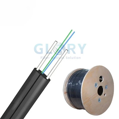
Aerial routes are where hardware mismatches appear first, because one pole line can carry cables with very different mechanics. Three constructions are common in rural access. ADSS (all-dielectric self-supporting) cable carries its tension through internal strength members. Figure-8 cable pairs the optical core with a separate messenger element that takes the load. Flat drop cable is usually lightly loaded and run on short spans with drop clamps. The FOA's outside plant installation guidance describes aerial cable types as installed in different ways, with ADSS needing matched anchoring and intermediate support.
Dead-end hardware and suspension hardware do different jobs. Dead-ends anchor the cable at terminations, corners and angle points, so they see the cable's tension. Suspension sets hold the cable at intermediate poles and take smaller, more varied loads. A 2024 ADSS accessories webinar from Incab America ties anchoring hardware to the cable's design tension and outside diameter, then moves on to supports, connections and vibration control. That material covers one vendor's product families, so its grades do not transfer to other suppliers' hardware. The matching method does transfer.
| Input | Why it matters |
|---|---|
| Cable type, outside diameter and tolerance | Clamp range must cover the actual cable, not a catalogue average |
| Strength member and sheath material | Sets how load is transferred into the clamp |
| Span, line angle, pole type and attachment method | Decides where dead-ends and suspension sets are needed |
| Design tension, wind and ice loads | Sets the load the hardware must be matched to |
| Installation and service temperature range | Needs its own statement for hardware and cable |
| Drawings and fit evidence | Confirms the match rather than assuming it |
For an aerial section, shortlist the anchoring and support hardware against the actual cable construction and route loads. Glory's clamp range can be reviewed once the cable diameter, load-bearing element, span geometry and tension requirements are defined.
The catalogue includes the JBG-2 dead-end anchor clamp for the anchoring role. Treat it as a candidate to match against your cable drawing, and ask for the confirmed cable range and load basis before ordering. Suspension or support sets should likewise be matched to the selected ADSS and requested separately; the ODN solution page is the place to start that conversation.

JBG-2 Dead-End Anchor Clamp
Aerial anchoring option for a cable-matched assembly. Specify the cable construction, diameter and design load.

H3 Fiber Optic Cable Dead Clamp
Wedge-type anchoring option for the hardware shortlist. Match the gripping arrangement and attachment to the selected cable.
Select PLC Splitters From the Optical Budget
The splitter is usually the largest single loss item in a village PON. The FOA treats the loss budget as the sum of fiber, splices, connectors and passive devices, and notes that test values depend on how they were measured. AFL's PLC splitter page likewise shows that loss and port specifications vary with split ratio and with whether connectors are included. A full ratio comparison is already covered in Glory's 1×16 versus 1×32 optical-budget comparison, so this section concentrates on how to read specifications for a village build.
Ratio, network generation and service rate cannot be settled from a village count alone. A lower ratio leaves more loss budget for long drops and extra splices. A higher ratio serves more subscribers per PON port but spends more of the budget. The calculation depends on the OLT optical class, the farthest and nearest subscribers, the number of splitter stages and the margin the operator wants to keep.
| Series | Ratio | Maximum insertion loss as published | Package and temperature statement | Fits when |
|---|---|---|---|---|
| 1×8 ABS Box | 1×8 | 10.8 dB excluding connector loss; 11.3 dB including it (separate tables) | ABS box; operating −40 to +85 °C | A protected enclosure has room for an integrated splitter package |
| 1×8 LGX Cassette | 1×8 | ≤ 12.8 dB | 29 × 130 × 127 mm; operating and storage −40 to +75 °C | The cabinet or panel offers compatible LGX slots and modular maintenance matters |
| Ribbon Fan-Out PLC | 1×2 to 1×64, plus 2×N options | 1×16: 13.7 dB; 1×32: 17.0 dB (table at 23 °C) | Basic, 900 µm SFF and ABS packaging | Ratio and interface need configuring to the design |
Reading note. Values come from each product page and use different series, packages and test conditions, so the rows are not a like-for-like ranking. Confirm wavelength, connector boundary, test reference plane and full-temperature limits in the quotation, and avoid carrying one series' figures over to another.
Assume the OLT optics and design rules allow a total path loss of 28 dB. Fiber, splices, other connection interfaces and design margin together take 12 dB. Acceptance limits for the splitter, each already including its agreed connection interfaces, are 14 dB for a 1×16 and 17.5 dB for a 1×32.
With the 1×16, 12 + 14 = 26 dB, leaving 2 dB. With the 1×32, 12 + 17.5 = 29.5 dB, which exceeds the budget by 1.5 dB. Under these assumptions the 1×32 design needs a change such as shorter reach, fewer splices, lower-loss parts or a different OLT class.
The example does not show that a 1×16 suits every rural network, or that a 1×32 never works. A real calculation uses the selected equipment class, minimum and maximum link attenuation, farthest and nearest subscribers, wavelength, temperature, splices and operating margin, and counts each connector only once.
A village PON needs a split plan that fits both the subscriber layout and the optical budget. Glory's ABS-box, LGX-cassette and fan-out PLC options provide different ways to package that plan; the ratio and enclosure must be selected for the actual installation.
For a protected-enclosure design, the 1×8 ABS box is a practical starting point because its page publishes separate loss tables with and without connectors, which puts the connector-boundary question on the table early. Where the design needs 1×16 or 1×32, or a different interface, the fan-out series is the route to a configured quotation.

1×8 ABS-Box PLC Splitter
Boxed 1×8 splitter for a protected enclosure. Specify connector interfaces and the insertion-loss test boundary.

1×8 LGX Cassette PLC Splitter
Modular 1×8 splitter for compatible LGX slots in panels and distribution frames. Check cassette fit and connector layout.
Plan Cold-Weather Installation and Field Acceptance
The national weather service's January 2026 bulletin records readings down to −40 °C in East Kazakhstan and Abay regions. That is a weather observation. It is not a product specification, and it does not show that anyone installed cable at that temperature.
Three temperatures need separate answers: operating, storage and installation. Component pages usually quote the first two. A splitter page listing −40 to +85 °C operating says something about that device, but the complete assembly also includes cable, closure seals, fasteners and the handling of fiber during work. An ABS splitter housing sits inside a closure, so sealing, fixing and installation limits belong to the closure and cable statements. Ask for installation-temperature limits for cable and closure in writing, and plan which activities, such as pulling, splicing and closure sealing, fall in the cold period.
Acceptance should be written into the order, not left to the end. The FOA's installation guidance stresses post-installation testing and documentation. A workable record set covers the as-built route and splitter locations, end-to-end loss for each tested path, the test wavelengths and method used, connector inspection results, and the date and conditions of the test. Because measured values depend on conditions, the record should name the reference method so later results can be compared with it.
Build an RFQ Around Route Data and Test Evidence
A strong RFQ gives suppliers inputs they can check, then asks for evidence they can be held to. The two lists below separate hardware inputs from splitter and ODN inputs, so each can be sent to the right technical contact.
Aerial hardware inputs
- Cable model, cross-section drawing, outside diameter and tolerance
- ADSS, figure-8 or flat drop construction
- Strength-member size and sheath material
- Span, angle, pole type and attachment method
- Design tension, wind and ice loads, installation and service temperatures
- Drawings, fit tests and acceptance requirements
PLC and ODN inputs
- PON type, OLT and ONU models, optical class
- Nearest and farthest subscriber distances, route map
- Planned subscribers, initial connections and expansion
- Splitter stages, ratio and location
- Interface, end-face type, pigtails, package and enclosure size
- Worst-port insertion loss, wavelength and temperature conditions, test reference plane
Add quantity, delivery location, required dates, labelling, packaging and document requirements. Ask suppliers to return drawings, a cable-to-hardware matching table, test reports with their conditions, and the installation-temperature limits of each item. Where several clamp models are candidates, such as the JBG-2 or the H3 dead clamp, list each with the cable range it is confirmed for. Ask suppliers to state local certification, stock and lead time explicitly rather than assuming any of them. To send these inputs to Glory, request a project-specific quotation.
Frequently Asked Questions
Does fiber reaching a village mean homes already have FTTH service?
No. Village fiber usually means a trunk or backhaul connection to a point in or near the settlement. Homes still need an OLT, a village ODN with splitters, distribution or drop cable and an ONT. Agreements and memoranda describe plans or cooperation, so connected homes need separate evidence such as acceptance records or service-activation data.
Should every rural PON use a 1×8 splitter?
No single ratio fits every village. A 1×8 spends less budget, while a 1×16 or 1×32 serves more subscribers per PON port and spends more. The right choice depends on OLT optical class, farthest user, splitter stages, splices and margin. Calculate the budget first, then pick the ratio; the 1×16 versus 1×32 comparison covers the trade-off.
Can an ADSS clamp also be used on a figure-eight drop cable?
Do not assume so. ADSS relies on the cable's own strength members, while figure-8 cable uses a separate messenger, so the load path into the clamp differs. Clamps are matched to cable diameter and design tension. Have the supplier confirm the specific clamp against your actual cable drawing before ordering.
Does a −40 °C component rating make the complete installation suitable for outdoor winter service?
No. A component rating describes that device. Cable, closure seals, fasteners, installation method and test procedure each have their own limits. Ask for system-level statements covering closure sealing, installation temperature and acceptance tests at the conditions you expect on site.
Take the Next Step
Planning a rural fiber access build? Share your cable specification, route loads, subscriber layout and optical-budget requirements with Glory Optical. Discuss compatible aerial hardware and PLC splitter configurations, and request the relevant drawings and test documentation.
Discuss Your Last-Mile ODN BOM
Sources and Scope
This guide uses publicly announced programme facts and general engineering practice. It does not suggest that any Glory component has been specified for, approved in or supplied to the Kazakh programme. Programme figures are plans, targets or dated reports, and may have changed since the dates shown. Check for later completion or delay announcements before relying on them.
- Ministry investment agreement announcement, 9 Jun 2025 - gov.kz (Russian)
- Ministry last-mile cooperation announcement, 4 Nov 2026 - gov.kz (Kazakh)
- Government national-projects progress statement, 20 Aug 2026 - primeminister.kz (Russian)
- Government 2027 coverage goal, 21 Oct 2025 - primeminister.kz (Russian)
- Abay region construction announcement, published 10 Jul 2026, updated 20 Aug 2026 - gov.kz (Russian)
- Kazhydromet, January 2026 records bulletin - PDF (Russian)
- World Bank, DARE financing approval, 22 Feb 2024 - worldbank.org
- Fiber Optic Association, outside plant installation - foa.org
- Fiber Optic Association, loss budget guidelines - foa.org
- Incab America, ADSS accessories webinar, 22 Feb 2024 - PDF
- AFL, planar lightwave circuit PLC splitters - aflglobal.com