I. Introduction: The Network Connection Hub
A Fiber Optic Termination Box (FTB) is the central point where fiber cables end. Its job is to organize connections, protect delicate splices and connectors, and let technicians access the network. You find FTBs in homes (FTTH), data centers, and company buildings. This guide shows you exactly how to install one correctly. Remember safety first: always wear laser safety glasses and watch for sharp edges.
II. Comprehensive Planning and Preparation
Site Assessment and Selection
Choose a stable, accessible location. Indoor spots need good wall/rack space and airflow. Outdoor boxes need strong weatherproofing (look for IP68 or NEMA 4X ratings) and UV resistance. Avoid areas with extreme temperature swings (>104°F/<40°F), high humidity (>85%), strong electrical interference (EMI), standing water, or poor structural support. Ensure enough workspace around the box.
Tools and Materials Checklist
Gather precision tools:
Fiber strippers (for buffer coatings)
High-quality cleaver (guarantees cleave angles <1 degree)
Fusion splicer (aim for splice loss <0.1 dB)
Visual Fault Locator (VFL)
Optical Loss Test Set (OLTS)
Torque screwdriver (0.3~0.5 Nm range)
99% Isopropyl alcohol & lint-free wipes
Cable ties/Velcro straps, cable guides
Heat shrink/mastic sealing kits (outdoor)
Labels, markers, documentation sheets
Verify all parts match: fiber type (SMF/MMF), connector styles (LC, SC), adapter types, splice protectors.
Safety First
Protect yourself: Anti-static wrist strap, certified laser safety glasses, gloves. Keep the work area spotless and dust-free. Cover vents or use a clean tent if needed. No food or drink near the work zone.
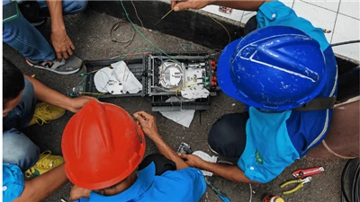
III. Step-by-Step Standard Installation Procedure
Step 1: Mounting and Cable Entry
Securely mount the box using proper hardware for the surface (brick, drywall, rack). Punch out only the needed cable entry ports. Install strain relief boots or grommets. Strip the incoming cable jacket carefully. Treat the strength member correctly (usually securing it inside the box). Fix the cable firmly outside the box before it enters.
Step 2: Fiber Preparation
Strip the colored buffer tubes. Separate individual fibers gently. Clean each fiber end-face thoroughly with alcohol and wipes before cleaving. Cleave the fiber using your precision cleaver following its instructions perfectly. Inspect the cleave immediately.
Step 3: Making the Connection
Fusion Splicing: Calibrate the splicer. Carefully align the fiber cores. Execute the splice. Slide the heat-shrink protector over the splice and shrink it. Place the protected splice securely in the tray clip. Record splice loss (target ≤0.05dB).
Mechanical Splicing: Use for quick repairs or restricted spaces. Follow the connector maker's steps precisely. Control alignment meticulously. Test loss immediately.
Step 4: Routing, Storage & Labeling
Coil fibers neatly in trays or around spools. Maintain the minimum bend radius always (≥30mm for SMF is critical). Secure fibers with clips. Install pigtails/connectors. Route patch cords using guides. Apply clear, durable labels to every port, cable, splice tray, and patch cord using a simple, consistent system (e.g., Building-Room-Port).
Step 5: Sealing, Grounding & First Check
For outdoor boxes, meticulously seal every entry point and enclosure seam using the provided kit. Ensure the grounding wire is properly connected to the designated point. Visually inspect inside: Are fibers secure? Bends okay? Labels clear? Use the VFL to check for basic light continuity on all paths.
IV. Key Considerations and Fault-Prevention Checklist
Fiber Protection Red Lines: NEVER:
Pull on exposed fibers.
Crush fibers under tools or heavy objects.
Bend fibers tighter than the minimum radius (≥30mm!).
Touch cleaned connector end-faces.
Cleanliness is Mandatory:
Clean tools, work surfaces, and your gloves. Inspect and clean every fiber end-face with a microscope (100x/200x) before connecting. Dust is the enemy.
Guarantee Splice Quality:
Only trained, certified technicians should splice. Calibrate fusion splicers daily. Reject splices >0.05dB loss without question.
Critical Parameters:
Enforce bend radius rules ruthlessly. Verify outdoor box seals pass IP68 water immersion tests. Torque all enclosure screws to spec (0.3-0.5 Nm).
Professionalism & Proof:
Follow TIA-568/ANSI/NECA 301 standards. Document everything: installer name, date, splice loss results (OLTS/OTDR), photos, label maps. This is your legal and technical proof.