1. The Starting Point: BBU in the Control Room

Every FTTA link begins at the Baseband Unit (BBU) , usually located in a shelter, equipment room, or outdoor cabinet. The BBU is responsible for processing the baseband digital signals, managing radio resources, and interfacing with the core network.
• Interface standards: Most BBUs use CPRI (Common Public Radio Interface) or the newer eCPRI to communicate with the remote unit. These protocols define the data rate, framing, and timing requirements.
• Optical output: The BBU sends out optical signals via small form‑factor pluggable (SFP/SFP+) transceivers. Common port types are LC duplex for legacy CPRI (up to 10G) and, increasingly, 25G interfaces requiring high‑performance fiber links.
Key takeaway: The control room is the "brain" of the site. From here, the optical signal begins its journey toward the antenna.
2. The Outdoor Fiber Cable – The Longest Journey
Once the signal leaves the BBU, it must travel to the RU, which may be located up to several hundred meters away-or even kilometers in some distributed architectures. The medium for this journey is outdoor‑rated fiber optic cable.
Why ordinary indoor cable won't work:
• Outdoor cable must resist UV radiation, temperature extremes (–40°C to +70°C), moisture, and mechanical stress (tensile and crush forces).
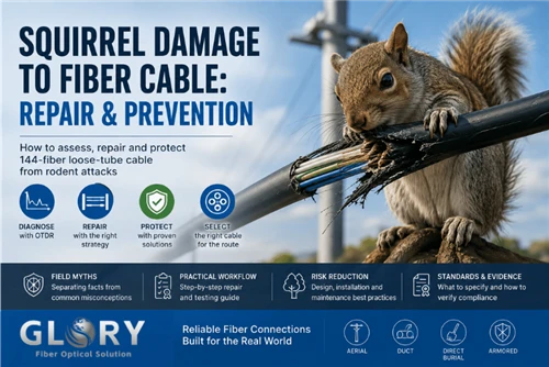
• It often includes armor (steel or FRP) to protect against rodents and accidental digging.
Typical fiber types for FTTA:
• G.652.D (standard single‑mode) for most links.
• G.657.A2 (bend‑insensitive) for tight spaces like cable trays or cramped enclosures.
Pro tip: For long outdoor runs, use cables with water‑blocking (dry or gel) and UV‑stabilized sheaths (usually black polyethylene). Many FTTA deployments also use hybrid cables that combine fiber with copper for remote power, but pure fiber is still the most common.
3. The Multiport Terminal Box – Fiber Distribution Point
When a single feeder cable needs to serve multiple RUs (e.g., a tower with three sectors), a Multiport Terminal Box comes into play. This rugged, weather‑proof enclosure is typically mounted on the tower leg, on a wall, or inside a pedestal.
Functions of the terminal box:
• Splitting: Contains a PLC splitter (e.g., 1:4 or 1:8) to distribute the incoming fiber to multiple RU ports.
• Termination: Provides hardened adapter ports (SC, LC, or MPO) for plug‑and‑play connection to drop cables leading to each RU.
• Protection: Sealed to IP68 to keep out dust and water; often includes strain relief for incoming and outgoing cables.
Why it matters: Without a terminal box, you would need individual feeder cables for every RU-expensive and space‑consuming. The box consolidates the fiber infrastructure, reduces cost, and simplifies maintenance.
4. The Critical Connection – CPRI ODVA and PDLC‑DLC
Between the terminal box and the RU, and often between the BBU and the outdoor cable, you will find specialized hardened connectors designed to withstand vibration, weather, and repeated mating.
Two common connector families in FTTA:
a) CPRI ODVA (Optical Distribution and Vibration‑resistant Assembly)
• Design: A push‑pull locking mechanism with a rugged over‑molded body. Often includes a protective dust cap and an O‑ring seal.
• Strengths: Excellent vibration resistance (tested to GR‑771), high pull‑out strength (≥200N), and IP68 rating when mated.
• Typical use: Tower‑top connections between the terminal box and the RU, especially in macro sites with strong wind or near traffic.
b) PDLC‑DLC (Push‑Pull LC – Duplex LC)
• Design: A standard LC connector modified with an extended push‑pull boot. No need to pinch small latches-just push to connect, pull to disconnect.
• Strengths: Easier for gloved hands, less prone to accidental unlocking, and compatible with standard LC adapters.
• Typical use: Indoor connections (BBU side) or outdoor in less demanding environments; also common in small cells.
Which one to choose?
• For tower‑top and outdoor high‑vibration environments, ODVA is the safer bet.
• For control rooms or sheltered locations, PDLC offers convenience and lower cost.
Both connector types should be factory‑terminated and tested for insertion loss (≤0.3dB typical) and return loss (≥55dB for UPC, ≥65dB for APC).
5. The Destination: Remote Unit (RU) on the Tower or Rooftop
Finally, the optical signal reaches the Remote Unit (RU) - also called RRU (Remote Radio Unit) or AAU (Active Antenna Unit). The RU houses the transceiver (optical‑to‑electrical conversion), power amplifiers, filters, and the antenna interface.
What happens inside the RU:
• The incoming fiber is terminated at a hardened connector port on the RU (often an ODVA or a weather‑sealed LC).
• The optical signal is converted back to electrical baseband, processed, up‑converted to RF, amplified, and transmitted through the antenna.
Key requirements for the RU‑side connection:
• Low insertion loss to preserve signal‑to‑noise ratio.
• Stable mechanical mating to prevent intermittent failures due to wind‑induced vibration.
• Ease of field replacement – a technician should be able to swap a faulty jumper without special tools.
6.Putting It All Together: A Typical FTTA Chain
Here's how the components connect in a real‑world macro site:
1.BBU (control room) → PDLC‑DLC patch cord → ODVA adapter panel (on the wall of the shelter)
2.Outdoor armored cable (pre‑connectorized with ODVA at both ends) runs up the tower.
3.At the tower top, the cable plugs into a Multiport Terminal Box (e.g., 1:4 splitter).
4.Four ODVA jumper cables go from the terminal box to three RUs (one spare).
5.Each RU is connected and ready to serve its sector.
The entire link from BBU to RU is passive (no active electronics in between) and pre‑connectorized (no field splicing). This approach drastically reduces installation time, improves quality, and simplifies future upgrades.
7.Why FTTA Matters for 5G Performance
Every component in this chain-cable, terminal box, connectors-introduces tiny amounts of insertion loss and potential points of failure. A poorly chosen connector or a damaged outdoor cable can degrade CPRI/eCPRI signals, leading to bit errors, retransmissions, and increased latency. In 5G, where latency targets are in the single‑digit milliseconds, even minor physical‑layer issues become critical.
Therefore, understanding the FTTA architecture is not just academic-it directly affects network reliability, deployment speed, and total cost of ownership.
8.Conclusion
From the BBU in the control room to the RU on the tower, each element of the FTTA chain has a specific job. The outdoor fiber cable provides the long‑haul path. The multiport terminal box distributes the signal. ODVA and PDLC connectors ensure reliable, weather‑proof connections. And the RU finishes the journey by turning light into radio waves.
When these components are chosen and installed correctly, the result is a robust, future‑ready 5G fronthaul that delivers on the promise of high speed, low latency, and uninterrupted connectivity.