What Is a Fiber Pigtail?
A fiber pigtail is a short length of optical fiber with a factory-installed connector on one end and bare, unterminated fiber on the other. The connector end plugs into an adapter port; the bare end is fusion- or mechanically spliced to a fiber in the incoming cable. That design choice - connectorize one end in the factory, splice the other in the field - moves the precision polishing work into a controlled environment and leaves only the splice for the technician on site.
The same component is also sold as a fiber optic pigtail, pigtail fiber cable, or simply pigtails. In practice the pigtail lives inside a fiber optic termination box, an ODF, or a splice tray, where the incoming feeder or drop fiber is spliced to the pigtail and the connector is presented on an adapter panel as a clean, testable port. It is the transition piece between bulk cable and a serviceable interface.
- A fiber pigtail has one factory-polished connector and one bare splice end. The connector plugs into a port; the bare end is fusion-spliced inside a tray.
- Factory polishing delivers lower, more consistent loss than field-terminated connectors. A fusion splice to a pigtail adds ~0.05 dB (typical); a field-terminated connector typically runs 0.3–0.75 dB. See the loss section for measurement methods and standards.
- Available in every common connector - LC, SC, FC, ST, E2000, MPO - in single-mode (OS2) and multimode (OM3/OM4/OM5), and in 900 µm tight-buffer or jacketed builds.
- All insertion-loss, return-loss, and bend-radius values in this guide are typical commercial targets and field guidance, not guaranteed minimums. Verify against the specific product datasheet and your link budget.
Why pigtails exist: the factory-polish advantage
Polishing a connector ferrule to a clean, geometrically correct endface is the hardest part of a termination, and it is the part most sensitive to operator skill. A factory grinds and machine-polishes the ferrule, then inspects the endface against IEC 61300-3-35 visual criteria (core, cladding, adhesive, and contact zones) and supplies a test report. A field-terminated connector - epoxy-and-polish or a mechanical fast connector - relies on a technician doing that same work crouched in a hand-hole with a headlamp. The pigtail removes that variable: the only field operation left is a fusion splice, which a modern core-aligning splicer makes repeatable. This is why pigtails dominate single-mode terminations where loss budget is tight.

Figure 1. Anatomy of a fiber pigtail - factory-polished connector end (left) and bare glass prepared for splicing (right). The 900 µm tight-buffer protects the glass between the two ends. [Replace with product photograph; suggested alt text above.]
Pigtail vs Patch Cord: The Distinction That Trips Buyers
This is the question most people actually have when they search for "pigtail," and getting it wrong is a common procurement error. The two parts look similar on a spec sheet but do opposite jobs.
| Attribute | Fiber pigtail | Patch cord (jumper) |
|---|---|---|
| Connectorized ends | One (other end bare) | Two |
| Primary use | Spliced to a cable fiber, then plugged into a port | Plugged into a port at both ends to route signal |
| Where it lives | Inside a splice tray / termination box / ODF | Between two pieces of equipment or panels |
| Jacket | Often unjacketed 900 µm tight buffer (lives protected in a tray) | Jacketed 2.0 / 3.0 mm (handled, routed, flexed) |
| Field operation | Fusion or mechanical splice | Plug in - no splice |
The clean mental model: a patch cord connects two ports that already exist; a pigtail creates a port where there wasn't one, by giving a spliced cable fiber a connector.
There is a well-known field shortcut: cut a duplex patch cord in half to get two pigtails. This is a legitimate recovery move - a patch cord can be tested end-to-end before cutting, whereas a bare-ended pigtail cannot be fully tested until spliced. But a halved patch cord is jacketed and bulkier than a purpose-built 900 µm pigtail, and it crowds a high-density tray. Order the correct part for production work.
Connector Types: LC, SC, FC, ST, E2000, MPO
A pigtail is specified first by its connector, because that is what must mate with the adapter panel on the other side. The ferrule - almost always precision zirconia ceramic in modern single-mode parts (geometry per IEC 61755-3-1 for SC/LC) - is common across types; what differs is the housing, latching mechanism, and density. Polish (PC / UPC / APC) is a separate axis covered in the loss section, and it matters more than housing type for PON work.
| Connector | Latch / mechanism | Footprint | Where it dominates |
|---|---|---|---|
| SC (Subscriber Connector) | Push-pull, square body | 2.5 mm ferrule | FTTH / GPON / XGS-PON access - handles well with gloves; the PON default |
| LC (Lucent Connector) | Push-pull, RJ-style latch | 1.25 mm ferrule (half the size of SC) | Data-center & high-density ODF panels - roughly doubles ports per rack unit |
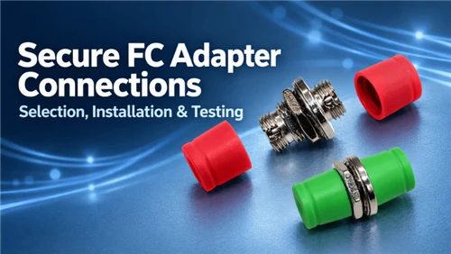
| FC (Ferrule Connector) | Threaded screw-on | 2.5 mm ferrule | Vibration-prone sites, test equipment, legacy CATV / telecom |
| ST (Straight Tip) | Bayonet twist-lock | 2.5 mm ferrule | Legacy multimode LAN / campus backbones |
| E2000 | Push-pull with spring-loaded dust shutter | 2.5 mm ferrule | Telecom backbone, CATV, high-power links - the shutter protects the endface when unmated |
| MPO / MTP | Push-pull multi-fiber ferrule | 12 / 24 fibers in one connector | 40G / 100G / 400G parallel-fiber data-center backbones |
For new FTTH and ODN work, SC dominates the access network and LC dominates the data center. E2000 is specified on high-power or frequently-handled telecom links - the integrated shutter means the endface is never left exposed. MPO pigtails are a distinct category: a single 12- or 24-fiber ferrule terminating a ribbon or breaking out into a backbone, used where individual LC ports would be unmanageable.

Figure 2. The six pigtail connector formats and their relative sizes. Left to right: SC, LC, FC, ST, E2000, MPO. [Replace with product comparison photograph; suggested alt text above.]
Single-Mode vs Multimode - and the Color Codes
The second axis is fiber type, and it is non-negotiable: a single-mode pigtail spliced to a multimode cable (or vice versa) produces a high-loss, unstable joint. Match the pigtail fiber to the cable fiber exactly.
Single-mode pigtails (OS1 / OS2)
A 9/125 µm core, used for long-distance and all PON/FTTH access work, operating at 1310 nm and 1550 nm (and 1490 / 1577 nm for GPON / XGS-PON downstream). Single-mode is the overwhelming majority of pigtail demand because access and transport networks are single-mode. Drop-side pigtails should use bend-insensitive G.657.A2 fiber (ITU-T G.657.A2), which tolerates a 7.5 mm long-term bend radius - critical inside the tight slack coils of a small termination box, where standard G.652.D fiber (30 mm radius) would macrobend and cause signal loss.
Multimode pigtails (OM1–OM5)
A 50/125 µm core (OM2–OM5) or legacy 62.5/125 µm (OM1), used for short-reach data-center and in-building links. OM3 and OM4 are the laser-optimized grades for 10G/40G/100G over short distances; OM5 adds short-wave division multiplexing (SWDM). A critical compatibility note: OM1's 62.5 µm core will not splice cleanly to a 50 µm OM2/3/4 fiber - the core-diameter mismatch alone causes significant loss, independent of splice quality.
Color codes - read the jacket and the boot
Jacket and connector-boot colors are the field shorthand for fiber type and polish. They follow ANSI/TIA-598-C and are worth committing to memory - they prevent the most common mismatch errors before a splicer is even powered on.
| Fiber type | Core (µm) | Jacket color | Typical use |
|---|---|---|---|
| Single-mode OS1 / OS2 | 9/125 | Yellow | FTTH, PON, long-haul |
| Multimode OM1 | 62.5/125 | Orange | Legacy LAN |
| Multimode OM2 | 50/125 | Orange | Legacy 1G LAN |
| Multimode OM3 | 50/125 | Aqua | 10G data center |
| Multimode OM4 | 50/125 | Aqua (or violet) | 40G/100G short-reach |
| Multimode OM5 | 50/125 | Lime green | SWDM 100G |
Independent of jacket color, the connector boot encodes polish per ANSI/TIA-598-C: blue = single-mode UPC, green = single-mode APC, beige/black = multimode. This is the fastest guard against the single worst pigtail mistake - mating an APC connector to a UPC port. The 8° angled APC endface physically cannot seat against a flat UPC endface; forcing it damages both ferrules and injects large loss. Green boot mates only green. We cover why PON requires APC in the loss section.
Jacket Material and Cable Structure
Most pigtails are 900 µm tight-buffer - a single fiber in a thin protective buffer, sometimes with a partial outer jacket that is stripped back before the splice. This is the standard build because the pigtail lives protected inside a tray. Where a pigtail must be handled or routed more aggressively, 2.0 mm or 3.0 mm jacketed builds are available.
Jacket compound - match it to the environment and fire code
- PVC (OFNR riser): economical default for general indoor use. Flexible, low cost, but emits dense toxic smoke when burned - not permitted in air-handling plenum spaces.
- LSZH (Low Smoke Zero Halogen): the right choice for occupied buildings, tunnels, transit, and any enclosed space where smoke toxicity is a life-safety concern. Now the default specification for most European and many Asian indoor installations.
- PE (Polyethylene): UV- and moisture-resistant for outdoor or exposed routing. Less common on pigtails specifically - pigtails usually sit indoors in a tray - but specified where the pigtail section is exposed before termination.
Multi-fiber pigtails come as a bundle (individual color-coded 900 µm fibers in a common outer tube) or a ribbon (fibers held in a flat array for mass-fusion splicing). Ribbon pigtails pair with a mass-fusion splicer to terminate 12 fibers in a single splice - a significant labor saver in high-count backbones.
How to Splice a Fiber Pigtail, Step by Step
Two splice methods are used in practice. Fusion splicing melts the two glass ends together with an electric arc, giving a permanent joint (~0.05 dB typical insertion loss, per FOA guidance). Mechanical splicing aligns the cleaved ends in an index-matching V-groove and clamps them - faster to set up but higher loss (0.2–0.5 dB typical) and less stable long-term. For single-mode PON or transport work, fusion is the standard; mechanical splices belong in temporary or emergency restoration only.
Fusion splice procedure
- Slide the heat-shrink sleeve on first.Thread the protector onto one fiberbeforestripping - forgetting it means re-cutting after the splice. Power and warm up the splicer.
- Strip the coatings.Remove the 900 µm buffer and 250 µm acrylate coating in small increments using the correct notch on the strip tool, exposing roughly 30 mm of bare 125 µm glass. A nicked fiber will fracture later under thermal cycling - strip cleanly or re-strip.
- Clean the bare glass.Wipe the bare fiber firmly with a lint-free wipe wetted with 99% isopropyl alcohol. A clean fiber produces a faint squeak. Invisible contamination becomes a bubble or dark spot in the splice and elevated loss.
- Cleave.Use a precision cleaver to produce a flat, perpendicular endface. A bad cleave angle is a leading cause of high splice estimates - re-cleave rather than splicing a poor face.
- Load and fuse.Seat both fibers in the splicer V-grooves, close the lid, and run the arc. A core-aligning splicer reports an estimated splice loss; target ≤0.05 dB on matched single-mode fiber (typical; per FOA guidance for fusion splice to pigtail).
- Protect the joint.Slide the heat-shrink sleeve over the bare splice so the joint sits centered on the stainless reinforcement rod, then shrink it in the splicer's oven. The fused joint is as fragile as a glass thread until protected.
- Lay into the tray.Coil slack above the minimum bend radius (≥7.5 mm for G.657.A2, ≥30 mm for G.652.D), seat the sleeve in its holder, and route the connector to the adapter panel. A tight coil is a macrobend loss you will chase later.
If the splicer's loss estimate is high, the fault is almost always upstream of the arc: dirty fiber, bad cleave, or a coating fragment. Re-cleave and re-clean before blaming the splicer or the pigtail. Re-splicing on the bench costs minutes; a high-loss joint discovered after the box is closed costs a truck roll.

Figure 3. The fusion-splice workflow from sleeve-on (step 1) to tray-seated (step 6). [Replace with installation photograph sequence; suggested alt text above.]
Fusion vs mechanical vs splice-on connector
| Method | Typical loss | Per-splice cost | Equipment cost | Best for |
|---|---|---|---|---|
| Fusion (to pigtail) | ~0.05 dB (typical) | Low | High (splicer) | Volume single-mode, PON, transport |
| Mechanical splice | 0.2–0.5 dB (typical) | Higher per unit | Low | Emergency / temporary restoration |
| Splice-on connector (SOC) | ~0.1 dB (typical) | Medium | High (splicer) | Connectorizing without a pigtail + tray |
Insertion Loss, Return Loss, and Why PON Demands APC
A pigtail introduces two loss contributions to the link: the splice (its bare end fused to the cable) and the mated connection (its connector seated in an adapter). Both count against the optical link budget, so both are specified and tested.
- Insertion loss (attenuation): the power lost across the joint or mated pair, measured per IEC 61300-3-34. Typical targets: ≤0.05 dB for a fusion splice; ≤0.3 dB per mated connector pair in the field. A connection reading above 0.5 dB is almost always contamination - clean the endface before swapping hardware.
- Return loss (reflectance): how much light reflects back toward the source. Higher (more negative dB) is better. Polish type is the primary determinant.
PC, UPC, APC - the polish decides return loss
The ferrule endface is polished one of three ways. PC (Physical Contact) is a basic domed polish. UPC (Ultra Physical Contact) is a finer domed polish, typically <−50 dB return loss. APC (Angled Physical Contact) polishes the endface at an 8° angle so reflected light is deflected into the cladding, achieving <−60 dB return loss.
For GPON and XGS-PON (per ITU-T G.984 and G.9807.1), APC is required - the PON laser is sensitive to back-reflection, and UPC's reflectance (~−50 dB) is insufficient to prevent laser destabilization. This is why FTTH pigtails are specified SC/APC (green boot) almost universally. An APC infrastructure is also forward-compatible: a GPON-to-XGS-PON OLT upgrade reuses the same pigtails and termination boxes without recabling.
In Glory factory acceptance testing, machine-polished SC/APC single-mode pigtails typically ship with insertion loss ≤0.2 dB and return loss ≤−60 dB per connector, with a per-unit test report. These are typical factory-measured values, not guaranteed minimums; verify against the current product datasheet.
When field crews report a "bad pigtail," returns analysis consistently identifies the root cause as endface contamination or APC-to-UPC mating - not manufacturing defects. Protective dust caps ship on every connector; a one-click cleaner and 400× inspection scope are standard items for this reason. The protocol is always: clean → inspect → mate.
Common Field Failures and How to Prevent Them
The same handful of faults account for most pigtail-related trouble tickets. All are preventable at the bench; all are expensive to diagnose after the enclosure is sealed.
| Failure | Root cause | How to prevent it |
|---|---|---|
| High insertion loss at mated port | Endface contamination: dust, fingerprint, oil | Clean and inspect every connector with a 1-click cleaner and 400× scope before mating - not after the link test fails. Follow IEC 61300-3-35 inspection zones. |
| Damaged ferrule endfaces | APC connector (green boot) forced into a UPC adapter (blue port) | Match boot colors strictly: green → green, blue → blue. Visually confirm before insertion. Do not force connectors. |
| Loss spike at the splice point | Mode mismatch: SM pigtail to MM cable, or OM1 (62.5 µm) to OM3 (50 µm) | Verify fiber type from jacket color and print legend before stripping. Match mode and core diameter exactly. |
| Fiber fracture weeks after installation | Bare glass nicked by wrong strip-tool notch or too-fast a pull | Use the correct notch size; strip in slow, controlled increments; inspect bare glass visually before cleaving. If in doubt, re-strip. |
| Macrobend loss / intermittent OTDR event | Slack coiled below minimum bend radius inside the tray | G.657.A2: ≥7.5 mm long-term bend radius. G.652.D: ≥30 mm. Coil generously; do not compress with tray lids. |
| Broken splice joint | Heat-shrink sleeve omitted, or not seated over the bare joint before heating | Thread the protector sleeve on before stripping - make it a mandatory first step. Confirm it fully covers the bare glass before running the heat cycle. |
Field Deployment Scenarios
The following scenarios show how connector, fiber grade, and jacket choices come together in three common deployment contexts.
Scenario 1 - FTTH Residential Drop (GPON)
A technician is terminating a 2-fiber G.657.A2 flat drop cable at a wall-mount termination box serving a residential subscriber.
Pigtails: SC/APC, OS2 9/125 G.657.A2, 900 µm tight buffer, LSZH
- Strip and cleave the drop cable. Fusion-splice one SC/APC pigtail to each fiber.
- Coil splice slack ≥7.5 mm bend radius in the tray; seat protectors.
- Connect each SC/APC port to the splitter output inside the termination box.
- Test with OTDR and power meter: splice ≤0.05 dB, mated connector pair ≤0.3 dB. Log measurements against fiber ID.
Scenario 2 - ODF Panel Expansion (Central Office)
A network team is adding 24 LC ports to an ODF panel for a new feeder cable splice point in a central office.
Pigtails: LC/APC single-mode, OS2, 900 µm, 12-color pack
- Fan out the 24-fiber feeder cable. Pre-label each pigtail with its fiber number before splicing.
- Fusion-splice each pigtail; seat each protector and coil ≥30 mm in the splice tray.
- Route LC connectors to the adapter panel; test each port with a power meter and light source.
- Record splice loss per fiber in the splicing log before closing the tray.
Scenario 3 - 40G / 100G Data Center Backbone
An engineer is building MPO-based trunk connections between leaf and spine switches in a structured cabling system.
Pigtails: MPO/MTP Type B, OM4 50/125, 12-fiber ribbon, aqua
- Confirm MPO polarity type (A / B / C) against the transceiver and panel spec before splicing.
- Mass-fuse the ribbon pigtail to the trunk cable with a 12-fiber splicer (all 12 in one arc).
- Test insertion loss per fiber using an MPO test probe; target ≤0.35 dB per mated MPO pair (ANSI/TIA-568 OM4 MPO channel budget).
- Document full fiber-to-port mapping; verify TX/RX polarity is correct at both ends before handoff.
Buyer's Selection Checklist
Six specifications fully define a pigtail order. Confirm each against the cable and equipment it will join - a mismatch on any one line means a high-loss or non-mating part.
- Fiber mode & grade.Single-mode (OS2) or multimode (OM3/OM4/OM5), matched exactly to the cable fiber. For FTTH drop side, specify bend-insensitive G.657.A2.
- Connector type.SC for PON/FTTH access, LC for high-density panels, FC/ST/E2000 where existing infrastructure or equipment dictates, MPO for parallel backbones.
- Polish.APC for any PON/FTTH link (required per ITU-T G.984/G.9807.1); UPC only where the mating port is confirmed UPC. Never mix polishes.
- Buffer / build.900 µm tight buffer for tray work; jacketed 2.0/3.0 mm if the pigtail will be handled, routed, or exposed before termination.
- Jacket compound.LSZH for occupied indoor spaces, tunnels, and transit; PVC/OFNR for general riser; PE where exposed to UV or moisture outdoors.
- Loss spec & test report.Specify ≤0.3 dB insertion loss and, for APC, ≤−60 dB return loss per connector, with a per-connector test report. Color-coded 12-strand packs (per ANSI/TIA-598-C) speed splicing and prevent crossed fibers.
Selection Decision Tree

Glory Fiber Pigtail Product Matrix
Glory manufactures the full pigtail range from a 20,000 m² ISO 9001:2015-certified facility in Ningbo, China, supplying telecom operators and ISPs in 50+ countries. Every connector is machine-polished and inspected to IEC 61300-3-35, and ships with a per-connector test report. Representative configurations are listed below; strand counts, lengths, jacket compounds, and connectors are customizable. Pigtails can be supplied pre-loaded in Glory termination boxes to reduce field labor. Verify current specifications against the individual product datasheet.
| Configuration | Fiber | Connector / polish | Build | Best for |
|---|---|---|---|---|
| SC/APC single-mode | OS2 9/125, G.657.A2 | SC/APC, <−60 dB RL (typical) | 900 µm, yellow, LSZH | FTTH / GPON / XGS-PON drops |
| LC/UPC single-mode | OS2 9/125 | LC/UPC | 900 µm, 12-color pack | High-density ODF / DC panels |
| LC multimode | OM3 / OM4 50/125 | LC/UPC | 900 µm, aqua | 10G/40G/100G short-reach |
| FC/APC single-mode | OS2 9/125 | FC/APC, threaded | 900 µm / jacketed | Test gear, vibration sites, CATV |
| E2000/APC single-mode | OS2 9/125 | E2000/APC, shutter | 900 µm, LSZH | Telecom backbone, high-power links |
| MPO/MTP | OM4 / OS2 | MPO, 12 / 24 fiber | Ribbon | 40G/100G/400G parallel backbones |
For a complete termination, pair Glory SC/APC pigtails with a fiber optic termination box and, for splitter-based PON designs, a Glory PLC splitter (1:8 / 1:16 / 1:32). Need both ends connectorized for equipment routing? See fiber patch cords.
People Also Ask - Straight Answers
-
Q: What is a fiber pigtail?
A: A short optical fiber with a factory-installed, machine-polished connector on one end and bare fiber on the other. The connector plugs into an adapter port; the bare end is fusion- or mechanically spliced to a fiber in the incoming cable, usually inside a splice tray or termination box. It converts a bulk cable fiber into a clean, testable port with lower, more consistent loss than a field-installed connector.
Q: What is the difference between a fiber pigtail and a patch cord?
A: A pigtail has one connector and one bare (splice) end; a patch cord has connectors on both ends. A patch cord connects two existing ports; a pigtail creates a port by giving a spliced cable fiber a connector. You can cut a duplex patch cord in half to make two pigtails - a known field shortcut - but a purpose-built 900 µm pigtail is slimmer and better suited to a tray.
Q: What connector types do fiber pigtails come in?
A: LC, SC, FC, ST, E2000, and MPO/MTP. SC dominates FTTH/PON access, LC dominates high-density data-center panels, FC suits vibration-prone and test applications, ST is legacy multimode, E2000 adds a protective shutter for telecom and high-power links, and MPO terminates 12–24 fibers at once for 40G/100G backbones.
Q: What is the difference between single-mode and multimode pigtails?
A: Single-mode pigtails use a 9/125 µm core (yellow jacket, OS1/OS2) for long distance and all PON/FTTH work. Multimode pigtails use a 50/125 µm core (OM2–OM5) or legacy 62.5/125 µm (OM1) for short-reach data-center links - OM3/OM4 are aqua, OM5 lime green, OM1/OM2 orange, per ANSI/TIA-598-C. The two types are not interchangeable; splicing across fiber grades causes high loss.
Q: How do you splice a fiber pigtail?
A: Slide the heat-shrink protector on first, strip the 900 µm buffer and 250 µm coating to expose ~30 mm of bare glass, clean with 99% isopropyl alcohol, cleave a flat endface, fuse in a core-aligning splicer (target ≤0.05 dB typical), then slide the protector over the joint, heat-shrink it, and coil the slack in the tray above the minimum bend radius. Mechanical splicing is an alternative for emergency work but runs 0.2–0.5 dB and is less stable.
Q: Why do PON and FTTH pigtails use SC/APC?
A: APC's 8° angled polish deflects reflected light into the cladding, giving return loss below −60 dB. GPON and XGS-PON lasers (per ITU-T G.984 and G.9807.1) are sensitive to back-reflection, and UPC (~−50 dB) is insufficient - it destabilizes the laser. SC handles well with gloves in the field, so SC/APC (green boot) is the FTTH default. An all-APC infrastructure also accommodates a future GPON-to-XGS-PON upgrade without recabling.
Q: Can I mate an APC pigtail with a UPC connector?
A: No. The 8° angled APC endface cannot seat flush against a flat UPC endface; forcing them damages both ferrules and injects large insertion loss. Boot colors are the safeguard - green (APC) mates only green, blue (UPC) mates only blue. Never mix polishes.
Q: What is the typical insertion loss of a fiber pigtail?
A: A fusion splice to a pigtail adds about 0.05 dB (typical), and a mated connector pair targets ≤0.3 dB in the field (per IEC 61300-3-34). Factory machine-polished single-mode pigtails typically ship at ≤0.2 dB insertion loss and ≤−60 dB return loss per connector. A reading above 0.5 dB at a single connection point is almost always endface contamination - clean and inspect before replacing hardware.
Q: How should I test a fiber pigtail?
A: Before splicing, inspect the factory connector endface with a 400× fiber inspection scope, checking all four IEC 61300-3-35 zones (core, cladding, adhesive, contact). After splicing, measure each splice event with an OTDR (target ≤0.05 dB) and end-to-end insertion loss with a calibrated power meter and light source (target ≤0.3 dB per mated pair). Any connection reading above 0.5 dB indicates contamination - clean the endface and re-test before closing the enclosure. Log all measurements against fiber ID and date.
Q: What length should a fiber pigtail be?
A: Standard lengths are 1 m and 1.5 m for most indoor termination boxes and ODF panels. The pigtail must be long enough to reach the adapter panel from the splice tray with enough slack to coil above the minimum bend radius, and to allow the connector to be unmated and re-mated without stressing the splice. For compact outdoor boxes, 0.9–1 m is typical; for tall ODF rack units, 1.5–2 m. A pigtail that is too short results in a force-loaded splice - always specify slightly longer than your measured path.
Q: Why is the bare end of a pigtail not jacketed?
A: Because it lives protected inside a splice tray. Most pigtails are 900 µm tight-buffer with at most a partial jacket over the buffered section, stripped before splicing. The slim profile fits high-density trays. Jacketed 2.0/3.0 mm builds exist for pigtails that must be handled or routed before termination.
Q: What jacket material should a fiber pigtail have?
A: LSZH for occupied indoor spaces, tunnels, and transit where fire smoke toxicity matters. PVC/OFNR for general indoor riser use at lower cost. PE for outdoor or exposed routing where UV and moisture resistance are needed. Match the compound to the installation environment and your local fire code.
Standards and References
- IEC 61300-3-35 - Fibre optic connectors: endface geometry and visual inspection criteria (the contamination/inspection standard for connector endfaces): iec.ch
- IEC 61300-3-34 - Fibre optic interconnecting devices: attenuation (insertion loss) measurement method: iec.ch
- IEC 61755-3-1 - Fibre optic connector optical interfaces: SC and LC connector geometry (ferrule dimensions and tolerances): iec.ch
- ANSI/TIA-598-C - Optical Fiber Cable Color Coding (jacket and boot colors: yellow = single-mode, aqua = OM3/OM4, green boot = APC, blue boot = UPC): tiaonline.org
- ITU-T G.652.D - Standard single-mode optical fibre and cable characteristics: itu.int
- ITU-T G.657.A2 - Bend-loss insensitive single-mode fibre (7.5 mm long-term bend radius; the standard for FTTH drop and pigtail fibre): itu.int
- ITU-T G.984 - Gigabit-capable Passive Optical Networks (GPON), APC return-loss requirements: itu.int
- ITU-T G.9807.1 - 10-Gigabit-capable symmetric Passive Optical Networks (XGS-PON): itu.int
- ANSI/TIA-568 - Balanced Twisted-Pair and Optical Fiber Cabling Standard (MPO channel insertion loss budgets for OM3/OM4): tiaonline.org
- The Fiber Optic Association (FOA) - Fusion splicing, connector cleaning, and inspection reference: thefoa.org