Is "Monomode Fiber" the Same as Single Mode Fiber?
Yes - monomode fiber and single mode fiber (SMF) refer to the same product. "Monomode" (and the French fibre monomode) is the standard term in European and French-language specifications, ITU-T documentation, and many Asian telecom procurement contracts. "Single mode" dominates North American and IEEE/TIA literature. On a bill of materials or factory floor, both terms describe the same 9/125 µm glass strand governed by ITU-T G.652.D or G.657.
Monomode fiber = single mode fiber (SMF). Core diameter 9 µm, carries one light mode, yellow jacket per TIA-598-C. Multimode fiber (MMF) has a 50 or 62.5 µm core, carries multiple modes simultaneously, and uses orange or aqua jackets.
This terminological split is the leading source of confusion in international fiber procurement. When a European operator specifies "monomode G.652.D" and a North American engineer reads "OS2 single mode," they are specifying the same glass.
The Physics in Plain Language: What "Mode" Actually Means
A mode in fiber optics is a distinct path - a specific angle and propagation pattern - at which light can travel through the core.
Single mode / monomode fiber has a core so narrow (9 µm - roughly one-tenth the width of a human hair) that physics enforces a single allowed propagation path. Light travels in a straight ray along the axis with no competing paths, and therefore no modal dispersion - the primary limitation on long-distance transmission.
Multimode fiber has a wider core (50 µm or 62.5 µm). Multiple rays travel simultaneously at different angles, reflecting off the cladding. This simplifies light coupling and permits lower-cost transceivers, but those rays arrive at the far end at slightly different times (differential group delay), blurring the signal. The effect becomes more significant as data rate or link distance increases.
Modern OM3/OM4/OM5 multimode uses a graded-index core profile: the glass is densest at the center and gradually less dense toward the outer edge. Outer-angle rays travel through the less-dense region at higher velocity, partially compensating for their longer path. The result, measured as Effective Modal Bandwidth (EMB), is what enables OM4 to support 100G over 100 meters - a distance OM1 or OM2 cannot reach at that speed.

Master Comparison Table: Monomode vs Multimode Fiber
| Parameter | Monomode / Single Mode (SMF) | Multimode (MMF) |
|---|---|---|
| Core diameter | 9 µm | 50 µm (OM3/OM4/OM5) · 62.5 µm (OM1/OM2) |
| Cladding diameter | 125 µm | 125 µm |
| Fiber standard | OS2 (ITU-T G.652.D / G.657.A2) | OM1–OM5 (IEC 60793-2-10) |
| Jacket color (TIA-598-C) | Yellow | Orange (OM1/OM2) · Aqua (OM3/OM4) · Lime green (OM5) |
| Connector boot color | Blue (UPC) · Green (APC) | Beige (OM1/OM2) · Aqua or Black (OM3/OM4) |
| Operating wavelength | 1310 nm · 1550 nm | 850 nm · 1300 nm |
| Light source | DFB/FP laser diode | VCSEL (850 nm) · LED (legacy) |
| Attenuation @ main wavelength | ≤0.36 dB/km @ 1310 nm · ≤0.22 dB/km @ 1550 nm | ≤3.0 dB/km @ 850 nm · ≤1.0 dB/km @ 1300 nm |
| Bandwidth | Essentially unlimited (no modal dispersion) | OM4: 4700 MHz·km EMB · OM5: 28,000 MHz·km |
| Typical max distance - 1G | 10–100 km (transceiver-dependent) | OM1: 275 m · OM4: 1,000 m |
| Typical max distance - 10G | 10 km (LR), 40 km (ER), 80 km (ZR) | OM3: 300 m · OM4: 400 m |
| Typical max distance - 100G | 10 km (LR4), 500 m (FR), 2 km (DR) | OM3: 70 m (SR4) · OM4: 100 m (SR4) · OM5: 150 m (SR4) |
| Typical max distance - 400G | 2 km (DR4), 10 km (FR4/LR4) | OM4: 100 m (SR8) · OM5: 150 m (SR8) |
| Transceiver cost (relative) | Higher (3–8× vs MMF at equivalent speed) | Lower baseline; VCSEL-based |
| Cable cost (relative) | Slightly lower per meter (simpler profile) | Slightly higher per meter (complex graded-index) |
| Installation difficulty | Higher (9 µm core, ≤0.2 µm endface tolerance, APC at 8°) | Lower (50 µm core, wider tolerance) |
| DWDM / WDM compatible | Yes (full CWDM/DWDM wavelength plan) | No (limited to 850 nm / SWDM on OM5) |
| Typical applications | FTTH/GPON, WAN, metro, campus backbone >500 m, 5G fronthaul/backhaul, AI data center inter-rack | Enterprise LAN, data center intra-row/TOR <400 m, SAN, in-building video |
| Bend-insensitive variant | G.657.A1 / G.657.A2 | OM4-Bend (limited market availability) |
| ITU / IEC standard | ITU-T G.652, G.655, G.657; IEC 60793-2-50 | IEC 60793-2-10 (G.651.1 for 50 µm) |
Transmission Distance: The Full Breakdown
Single Mode (OS2) Distance Capabilities
OS2 fiber (ITU-T G.652.D, the low-water-peak outdoor variant) achieves long reach through two mechanisms: the 9 µm core eliminates modal dispersion entirely, and the silica glass composition achieves low published attenuation - as low as 0.22 dB/km at 1550 nm under standard test conditions per IEC 60793-2-50.
Practical OS2 distances depend on the transceiver type, connector count, splice count, and link budget. The distances below reflect published IEEE 802.3 and MSA specifications; actual reach varies with installation quality and optical budget margin:
| Transceiver Type | Speed | Specification Distance |
|---|---|---|
| SFP+ LR | 10G | 10 km |
| SFP+ ER | 10G | 40 km |
| SFP+ ZR | 10G | 80 km |
| QSFP28 LR4 | 100G | 10 km |
| QSFP28 DR (single-lambda) | 100G | 500 m |
| QSFP28 FR | 100G | 2 km |
| QSFP-DD DR4 | 400G | 500 m |
| QSFP-DD FR4 | 400G | 2 km |
| QSFP-DD LR4 | 400G | 10 km |
| QSFP-DD ZR (coherent) | 400G | 120 km |
For FTTH/GPON networks, standard XGS-PON (10G-PON) runs OS2 G.657.A2 bend-insensitive single mode fiber from the OLT to the ONT over distances up to 20 km, with up to 1:128 passive split ratio using PLC splitters. PON access networks are exclusively single mode territory.
Multimode Distance by OM Generation
| OM Grade | Core (µm) | Jacket | 1G | 10G | 40G | 100G |
|---|---|---|---|---|---|---|
| OM1 | 62.5 | Orange | 275 m | 33 m | - | - |
| OM2 | 50 | Orange | 550 m | 82 m | - | - |
| OM3 | 50 | Aqua | 1,000 m | 300 m | 100 m | 70 m (SR4) |
| OM4 | 50 | Aqua | 1,000 m | 400 m | 150 m | 100 m (SR4) |
| OM5 | 50 | Lime green | 1,000 m | 400 m | 150 m | 150 m (SR4/SWDM4) |
OM5 does not extend 850 nm SR/SR4 reach beyond OM4 levels. Its additional bandwidth appears only with SWDM4 transceivers using four wavelengths (850–950 nm), enabling 400G over eight fibers instead of 32. For networks still running 10G–100G SR optics, OM5 offers no practical distance advantage over OM4.
OM1/OM2 in 2026: These grades are effectively end-of-life for new deployments. Infrastructure inherited with orange-jacketed 62.5 µm fiber should be budgeted for re-cabling before deploying anything faster than 1G. The modal bandwidth does not support modern speeds at useful distances regardless of transceiver selection.
Why Modal Dispersion Limits Multimode at Higher Speeds
A recurring error in capacity planning is assuming that because a given OM grade supports 100G, it will support 200G or 400G at proportionally reduced distances. It does not work that way. Modal dispersion scales with data rate non-linearly. At 10G over 300 m, OM4's EMB provides comfortable margin. At 100G over 100 m, that margin shrinks considerably. At 400G, parallel optics architectures (SR8, FR8) distribute the load across multiple fibers precisely because no single-lambda solution can sustain 400G PAM-4 over multimode at practical distances. Optical budget analysis at the target speed is required before specifying multimode for any link approaching its rated distance limits.
Bandwidth, Attenuation, and the Link Budget
Attenuation Values You Should Know
| Fiber Type | Wavelength | Maximum Attenuation (published standard) |
|---|---|---|
| OS2 SMF (G.652.D) | 1310 nm | ≤0.36 dB/km |
| OS2 SMF (G.652.D) | 1550 nm | ≤0.22 dB/km |
| OM3 MMF | 850 nm | ≤3.0 dB/km |
| OM4 MMF | 850 nm | ≤3.0 dB/km |
| G.657.A2 FTTH drop | 1310 nm | ≤0.40 dB/km |
| G.657.A2 FTTH drop | 1550 nm | ≤0.30 dB/km |
Per published fiber standards, OS2 attenuation at 1550 nm is approximately 15× lower than OM4 attenuation at 850 nm. This difference is the principal reason single mode fiber is the only viable option for links beyond 500 meters.
Quick Link Budget - A Worked Example
A link budget is a one-way power accounting check: does the received signal fall within the receiver's sensitivity range with enough margin? The following simplified examples use typical published transceiver values; actual component performance should be verified against manufacturer datasheets for any production deployment.

Both examples are within specification - the SMF link covers 25× the distance with more optical margin. Network architects who default to SMF at distances where MMF would technically work are trading transceiver cost for link headroom and upgrade flexibility, which is a defensible design choice in many environments.
Color Identification: The Visual Quick Reference
Per TIA-598-C (North American standard) and the aligned IEC 60304 / CENELEC EN 50173, cable jacket color is the primary visual identifier:
| Jacket Color | Fiber Type | Standard |
|---|---|---|
| Yellow | Single mode OS1/OS2 (monomode) | TIA-598-C, Table 3 |
| Orange | Multimode OM1 (62.5 µm) · OM2 (50 µm) | TIA-598-C |
| Aqua / Teal | Multimode OM3 · OM4 (laser-optimized 50 µm) | TIA-598-C (2005 revision) |
| Lime green | Multimode OM5 (wideband) | TIA-492-AAAE / ISO/IEC 11801-3 |
| Black | Outdoor cable - any fiber type; read the print | - |
| Blue | Indoor single mode, tight-buffered (varies by vendor) | Regional variations |
Connector boot color provides a second layer of identification:
| Boot Color | Meaning |
|---|---|
| Blue | Single mode UPC (Ultra Physical Contact) |
| Green | Single mode APC (Angled Physical Contact, 8°) |
| Beige | Multimode OM1/OM2 |
| Black | Multimode OM3/OM4 (many vendors) |
| Aqua | Multimode OM3/OM4 (alternate convention) |
| Lime green | Multimode OM5 |
APC connectors (green boot) use an 8° angled polish that is physically incompatible with UPC (flat, blue boot) endfaces. Mating them does not form a proper connection: it produces elevated return loss and can damage both endfaces, requiring re-polishing or connector replacement. In FTTH deployments, the subscriber-side adapter is almost always SC/APC, while upstream patch panel connections may be SC/UPC. Verify polish type before any connection, particularly when working across equipment from different vendors or different build phases. Glory's fiber optic patch cords are labeled SC/APC or SC/UPC on every product listing to prevent this error.
Black outdoor jacket is a UV-protection choice, not a fiber type indicator. Always read the legend printed on the cable sheath (e.g., "OS2 G.652.D" or "OM4 50/125"). Assuming a black cable is single mode because it arrived from the telecom contractor - or because the previous segment was single mode - is a recurring source of mismatched transceivers during network upgrades.
Light Source Technology - Why It Drives the Cost Gap
The cost difference between SMF and MMF systems lies primarily in the optical transceivers, not the cable.
Multimode transceivers use VCSEL (Vertical-Cavity Surface-Emitting Lasers) at 850 nm. VCSELs are manufactured in 2D wafer arrays, making them cost-effective to produce at volume. Published market pricing for 10G SFP+ SR VCSEL transceivers is typically in the $15–$40 range at volume; 100G QSFP28 SR4 runs approximately $80–$150. Actual pricing varies by vendor, quantity, and market conditions.
Single mode transceivers require DFB (Distributed Feedback) or FP (Fabry-Pérot) laser diodes operating at 1310 nm or 1550 nm. These lasers require precise thermal stabilization and coupling into the 9 µm core. Published market pricing for 10G SFP+ LR is typically $60–$120; 100G QSFP28 LR4 runs approximately $400–$800 at volume. All transceiver pricing should be confirmed with your supplier at time of purchase; the figures above reflect general market ranges and are not guaranteed.
The 2026 shift - silicon photonics: Co-packaged optics (CPO) and silicon photonics integration are reducing SMF transceiver costs for 400G and 800G deployments. Platforms such as NVIDIA Spectrum-X and Broadcom Tomahawk5 are designed around SMF infrastructure. For GPU cluster deployments, the total cost premium of SMF over MMF at 200–400 m has narrowed from the historical 5–8× to approximately 2–3× in current production pricing, though this varies significantly by vendor and volume tier.
Total Cost of Ownership: 3-Year TCO Analysis
Scenario A: 48-port 10G Access Layer, 200-meter Links (Enterprise Campus)
| Cost Element | OM4 MMF | OS2 SMF |
|---|---|---|
| Fiber cable (48 runs × 200 m) | ~$2,880 | ~$2,400 |
| SFP+ transceivers (96 units) | ~$3,840 (SR) | ~$9,600 (LR) |
| Installation labor | ~$4,800 (MMF, easier termination) | ~$7,200 (SMF, precision required) |
| Year 1 total (estimated) | ~$11,520 | ~$19,200 |
| Year 3 upgrade to 25G (96 transceivers) | ~$9,600 (SR) | ~$14,400 (LR) |
| Re-cable needed? | No | No |
| 3-year TCO (estimated) | ~$21,120 | ~$33,600 |
Scenario B: 48-port 100G Spine Layer, 500-meter Links (Data Center Backbone)
| Cost Element | OM4 MMF | OS2 SMF |
|---|---|---|
| Fiber cable (48 runs × 500 m) | ~$17,280 | ~$14,400 |
| QSFP28 transceivers (96 units) | Cannot reach 500 m with SR4 | ~$48,000 (LR4) |
| Re-cable or extender needed | Yes (~$8,640 for SR4 + media converters) | No |
| 3-year TCO (estimated) | ~$47,520+ | ~$62,400 |
Engineering rule of thumb: If your links are consistently under 200 m and 400G+ is not on the three-year roadmap, OM4 typically delivers better initial ROI in this type of model. If any link exceeds 300 m, or if your roadmap includes 400G within three years, OS2 SMF avoids re-cabling costs that typically exceed the transceiver premium over the infrastructure lifetime.
Deployment Example: OM1 Migration on a University Campus
The following describes a scenario representative of projects encountered during OM1/OM2 infrastructure upgrades at campus facilities. Details are composited and anonymized.
A mid-sized university campus with a building stock from the early 2000s had approximately 18 km of 62.5 µm OM1 multimode fiber installed in conduit between 22 buildings. The network had been running 1G-Ethernet without issues. When the IT team specified a campus-wide upgrade to 10G access switching, fiber testing showed the existing OM1 cable would support 10G SR only to approximately 30–33 m per specification - a fraction of the typical inter-building runs of 80–350 m.
The initial plan assumed that replacing switches and transceivers would be sufficient. It was not. Options evaluated included: (1) SMF LR transceivers launched into the existing OM1 cable - tested and found to introduce a launch penalty in the range of 3–4 dB depending on launch conditions and connector quality, insufficient for reliable 10G links at the longer runs; (2) fiber media converters at each building entry point - functional but added latency, required power, and created additional failure points; (3) re-cabling select inter-building routes with OS2 SMF, retaining OM1 for internal horizontal runs where 1G remained acceptable.
The outcome was a phased plan: high-traffic inter-building routes were re-cabled with OS2, with the rest deferred until building renovation provided conduit access. The project cost was approximately 40% higher than the initial estimate, with re-cabling labor accounting for most of the overrun. The lesson consistently drawn from this type of migration is that the fiber plant cost is driven almost entirely by conduit access and labor - not by the cable itself - and that specifying OS2 on initial installation adds marginal cost relative to the re-cabling expense when the infrastructure turns out to be the limiting factor.
Application Scenarios: Where Each Technology Excels
Single Mode / Monomode Fiber - Ideal Use Cases
FTTH/FTTB/FTTx Networks (PON)
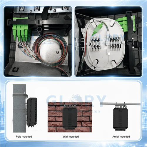
GPON and XGS-PON are single mode technologies from OLT to ONT. The entire ODN - from central office through outdoor fiber cable, PLC splitters (typically 1:32 or 1:64), fiber termination boxes, drop cables, and fiber connectors to the subscriber's ONT - is 100% OS2 or G.657.A2 single mode. Multimode fiber has no role in a PON access network.
Glory's G.657.A2 FTTH drop cables are specified for this application. The G.657.A2 specification permits a minimum bend radius of 7.5 mm (versus 30 mm for standard G.652.D), which is necessary for routing drops around door frames and through conduit bends at subscriber premises without incurring bend-induced attenuation.
5G Fronthaul, Midhaul, Backhaul
Open RAN architectures require fiber from the Central Unit (CU) through the Distributed Unit (DU) to the Radio Unit (RU). DU-to-RU fronthaul spans of 10–20 km are common in dense urban deployments. Only single mode fiber meets the distance and latency requirements. Glory's outdoor fiber optic cables include armored and aerial configurations used in 5G fronthaul infrastructure.
Campus Backbone (>300–500 m)
Inter-building links on university, corporate, or hospital campuses exceeding 300 m are most cost-effectively served by OS2 SMF. Speed upgrades (1G → 10G → 40G → 100G → 400G) can be accomplished by swapping transceivers; the fiber does not need to change. This upgrade-in-place benefit is the primary justification for specifying SMF on initial installation even where the current speed requirement could be met by OM4.
WAN, Metro, Long-Haul, Submarine
Exclusively single mode. DWDM systems carry 80–100 channels of 100G–400G on a single fiber pair over spans of thousands of kilometers. No multimode technology is applicable.
AI GPU Cluster Interconnect (>100 m inter-rack)
Hyperscale GPU clusters increasingly specify OS2 single mode for inter-rack links beyond 100 m. At 1.6 Tbps port speeds on the roadmap for coming generations, VCSEL-based MMF optics cannot provide a viable upgrade path. Glory's MTP/MPO fiber cable assemblies are available in both OS2 and OM4 configurations.
Multimode Fiber - Ideal Use Cases
Enterprise In-Building LAN (≤300 m)
OM4 remains cost-effective for horizontal cabling between the telecommunications room and access switches within a single building. At 10G-to-the-desk, the VCSEL transceiver cost advantage over SMF is typically 60–70% per port, depending on current market pricing.
Data Center Top-of-Rack to EOR/MOR Aggregation (≤150 m)
Standard hyperscale data center architectures where the ToR-to-EOR switch link is 20–80 m favor OM4 with 40G SR4 or 100G SR4 on direct cost. Glory's data center cabling includes OM4 MPO trunk cables pre-terminated for rapid deployment.
Storage Area Networks (SAN)
Fibre Channel at 32G FC and 64G FC operates over OM4 with distances up to 100 m. Controlled, short-reach storage environments are suited to multimode.
In-Building Security and CCTV
IP camera backbones in industrial and commercial facilities frequently use multimode fiber for video traffic, where the wider core tolerance to dust and contamination simplifies field maintenance in high-particulate environments.
The 2026 AI Infrastructure Consideration
GPU-dense AI training clusters are shifting the conventional SMF/MMF boundary in data center design. The traditional rule of thumb - multimode for all links under 150 m - is being revisited for several reasons:
- Fiber count per link: An 800G link over OM4 (SR8) requires 8 fibers. An equivalent 800G link over OS2 using DR8 or FR8 uses 2 fibers. In a cluster with thousands of inter-switch links, reducing fiber count materially simplifies cable management and splice closure planning.
- Upgrade path: Moving from 400G to 800G in an OM4 plant may require re-cabling for some link types. An OS2 plant typically requires only transceiver replacement.
- Power per port: At 400G, PAM-4 VCSEL modulation overhead can exceed the power consumption of equivalent SMF DR/FR optics in some current-generation implementations, though this advantage varies by transceiver design and should be verified for specific hardware.
For new AI or HPC data center design in 2026, an OS2 SMF backbone for spine and inter-rack links, with OM4 retained for legacy or short-reach connections where existing infrastructure is in place, reflects the direction of current hyperscaler deployments. The economics of this choice depend on specific hardware pricing at time of procurement.
The Selection Decision Tree

Common Mistakes to Avoid
1. Connecting a single mode SFP into multimode fiber
Launching a single mode DFB laser into a multimode fiber core typically introduces a launch penalty varying from 3–4 dB depending on the specific transceiver output characteristics, fiber path, and connector quality - sufficient to produce an unreliable link. The reverse - a VCSEL-based MMF transceiver into SMF - typically results in loss exceeding 20 dB as the VCSEL beam fails to couple meaningfully into the 9 µm core. The link will not establish. These fiber types are not interchangeable regardless of physical connector compatibility.
2. Mixing APC and UPC connectors on the same link
The 8° angled endface of an APC connector is mechanically incompatible with a flat UPC endface. Contact between mismatched polishes can produce insertion loss of 4+ dB and risks damaging both endfaces. Verify connector polish type before any connection in a mixed-equipment environment. Glory's fiber optic pigtails and patch cords carry clear polish-type labeling on every product listing.
3. Not cleaning SMF connectors
A 9 µm SMF core covers approximately 64 µm² of cross-sectional area. A single contamination particle of 5 µm diameter occupies a significant fraction of the light-carrying region. Per IEC 61300-3-35 Grade B cleanliness standards, the endface contact zone must be free of particles ≥3 µm. Clean every SMF connector with an IEC 61755-3-31 compliant cleaner before every connection and verify with a fiber inspection scope where practical. This requirement is not optional on SMF; it is what separates a reliable link from a borderline one.
4. Confusing OS1 with OS2
Both are single mode, but OS1 is a tight-buffered indoor cable specification (typically G.652.A/B) with a higher maximum attenuation allowance (1.0 dB/km at 1310 nm) than OS2 (0.4 dB/km at 1310 nm). OS2 is the appropriate specification for outdoor cables and any run where link budget margin is material. Specify OS2 for all new installations.
5. Assuming outdoor cable is single mode because it is black
Black jacket = UV-resistant outer sheath. It does not indicate fiber type. Read the legend printed on the cable (e.g., "G.652.D" or "OM4 50/125"). Glory's outdoor cables print the fiber specification on the jacket.
6. Specifying OM3 to save 10% on cable cost
OM3 costs approximately 10% less per meter than OM4 but cannot meet OM4 distance specifications at 40G or 100G. If the network ever operates at those speeds over the infrastructure lifetime, OM3 cable will need to be replaced. The re-cabling cost typically exceeds the initial savings by a wide margin when labor and conduit access are factored in.
Glory Optical Fiber Product Matrix
Glory Optical Communication (Ningbo, China) manufactures FTTH/FTTx ODN components and cable assemblies to ISO 9001:2015, IEC, TIA, and ITU-T specifications. Products are supplied to telecom operators and ISPs in over 50 countries.
Single Mode (Monomode) Products
- FTTH Drop Cables - G.657.A2 Bend-Insensitive SMF: For GPON and XGS-PON subscriber drops. LSZH, PE, and figure-8 aerial configurations; 7.5 mm minimum bend radius. Custom color and print available under our OEM program.
- Indoor SMF Cables - OS2 / G.652.D: Tight-buffered simplex, duplex, and distribution cables; OFNR and OFNP rated variants for riser and plenum environments.
- Outdoor SMF Cables - G.652.D / G.657.A2: ADSS aerial, armored direct-burial, and micro-duct configurations for campus, municipal, and 5G fronthaul deployments.
- SMF Pigtails - SC/APC, LC/APC, SC/UPC, LC/UPC: OS2, factory-terminated. IEC 61755-3-31 endface cleanliness.
- SMF Patch Cords - SC/APC, LC/APC, SC/UPC, LC/UPC, MPO: Yellow jacket, LSZH or PVC, 0.5–30 m standard lengths; custom lengths available.
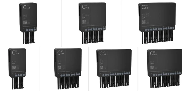
- PLC Splitters - 1:2 to 1:128: Single mode, for GPON/XGS-PON PON networks. Available as bare, ABS mini-module, LGX cassette, and rack-mount enclosure formats.
- Fiber Optic Adapters - SC, LC, FC, ST, MPO: SMF and MMF variants; SC/APC for FTTH subscriber wall outlets.
Multimode Products
- OM3/OM4 Patch Cords - LC/UPC, SC/UPC, MPO: LC-LC, SC-SC, LC-SC, and MPO configurations; aqua jacket for data center horizontal and backbone runs.
- MTP/MPO Trunk Cables and Breakout Assemblies - OS2 & OM4: Pre-terminated 12F and 24F assemblies for structured data center cabling. Method A, B, and C polarity variants available.
- Fiber Optic Patch Panels - 1U/2U/4U Rack Mount: LC, SC, and MPO adapter plates; accommodates SMF and MMF in the same enclosure.
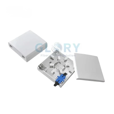
- Fiber Optic Termination Boxes and Wall Outlets: ODN distribution hardware for FTTH subscriber terminations.
OEM and ODM services are available - custom lengths, jacket colors, laser-printed legends, bundled packaging, and private-label connectors. Contact sales@gloryoptic.com or submit a specification enquiry.
People Also Ask - Straight Answers
-
Q: Is monomode the same as single mode fiber?
A: Yes. Monomode fiber and single mode fiber (SMF) are the same product. "Monomode" is the preferred term in European (ITU-T, CENELEC) and French-language specifications; "single mode" is used in North American (TIA/IEEE) standards.
Q: What is the maximum distance for multimode fiber?
A: Depends on OM grade and data rate. OM4 supports 10G up to 400 m, 100G up to 100 m (SR4), and 400G up to 100 m (SR8). For longer distances at any of those speeds, single mode fiber is required. Verify with your transceiver manufacturer's link budget tool for the specific hardware.
Q: Can I use a single mode SFP with multimode fiber?
A: It is not recommended and will result in unreliable performance. An SMF DFB laser launched into MMF introduces a launch penalty typically in the 3–4 dB range depending on launch conditions. The reverse - a VCSEL-based MMF transceiver into SMF - results in loss typically exceeding 20 dB; the link will not function. The fiber types are not interchangeable.
Q: What color is single mode (monomode) fiber cable?
A: Per TIA-598-C, single mode cables have a yellow jacket. Connectors use a blue boot (UPC) or green boot (APC). Multimode fiber uses orange (OM1/OM2), aqua (OM3/OM4), or lime green (OM5) jackets. Outdoor cable of any fiber type is typically black; always read the printed legend.
Q: Is single mode or multimode fiber better for data centers?
A: Both have roles, determined by link distance and speed requirements. OM4 is generally cost-effective for links under 150–200 m with 100G SR4 optics at current transceiver pricing. OS2 single mode is required for links over 300 m and is increasingly selected for new 400G and 800G AI data center deployments where fiber count and upgrade path considerations favor SMF.
Q: Can I mix single mode and multimode fiber in the same network?
A: They can coexist in different segments. You cannot directly interconnect SMF and MMF without a fiber media converter - the core size mismatch produces insertion loss that will prevent link establishment on any practical link. A media converter adds cost, power, latency, and a failure point.
Q: What is the difference between OS1 and OS2 fiber?
A: Both are single mode. OS1 is a tight-buffered indoor cable specification (max attenuation 1.0 dB/km at 1310 nm per the OS1 category). OS2 has a lower attenuation specification (max 0.4 dB/km at 1310 nm; typically 0.22 dB/km at 1550 nm) and is the standard for outdoor and long-reach applications. Specify OS2 for all new installations.
Q: What is G.657.A2 fiber and why is it used for FTTH?
A: G.657.A2 is a bend-insensitive variant of single mode fiber, compatible with G.652.D, with a minimum bend radius of 7.5 mm versus 30 mm for standard G.652.D. Standard G.652.D cannot be routed around door frames and through tight building conduit bends without incurring bend-induced attenuation. G.657.A2 eliminates that constraint for FTTH drop installation.
Standards and References
- ITU-T Recommendation G.652 - Characteristics of a single-mode optical fibre and cable: itu.int
- ITU-T Recommendation G.657 - Characteristics of a bending-loss insensitive single-mode optical fibre: itu.int
- IEC 60793-2-10 - Optical fibres: Product specifications - Category A1 multimode fibres: iec.ch
- IEC 60793-2-50 - Optical fibres: Product specifications - Category B single-mode fibres: iec.ch
- ANSI/TIA-598-C - Optical Fiber Cable Color Coding: tiaonline.org
- The Fiber Optic Association - Color Code Reference: thefoa.org
- NVIDIA GPU Cluster Fiber Documentation (400G-OSFP User Guide, 2025): docs.nvidia.com
- IEEE 802.3 Ethernet Standards - 802.3ae (10G), 802.3ba (40G/100G), 802.3bs (200G/400G): ieee.org
- IEC 61300-3-35 - Optical fibre connectors - Endface geometry and visual inspection: iec.ch