Quick Answer: Choose by Network Scenario, Not Only by Port Count
If you are asking how to choose a fiber distribution box for FTTH projects, start with the network scenario rather than the number printed on the adapter panel. A 16-port box may be right for one outdoor access node and wrong for another if the splice tray, PLC splitter space, cable glands or mounting bracket do not match the ODN design.
| Project scenario | Common port count | Splitter option | Mounting | Key selection focus |
|---|---|---|---|---|
| Single-family drop point | 4–8 ports | 1×4 or 1×8 PLC | Wall or pole | Cable diameter, gland size, port sealing and spare ports. |
| MDU corridor or riser | 16–24 ports | 1×8 or 1×16 | Wall or cabinet | Splice tray count, slack storage, labels and access control. |
| Outdoor wall or pole access node | 8–16 ports | 1×8 or 1×16 | Pole or wall | IP rating, UV resistance, cable gland range and strain relief. |
| High-density FTTB or building entrance | 24 ports or more | 1×16 or 1×32 after loss-budget check | Cabinet or wall | Port map, maintenance space, future expansion and test records. |

5-Step Fiber Distribution Box Selection Flow
Use this flow before sending the RFQ. It turns the project layout into a box specification and reduces the chance of receiving a product that looks right on the datasheet but fails in the field.
In FTTH box inquiries, the most common missing items are not the obvious ones. Buyers usually provide port count and adapter type, but often omit feeder cable diameter, drop cable diameter, splitter form factor and mounting method. Those four items decide whether the box can actually be installed.
What Is a Fiber Distribution Box in an FTTH Network?
Where it sits in the ODN
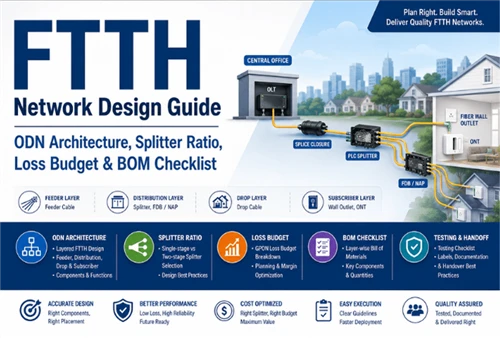
A fiber distribution box sits in the distribution layer of an optical distribution network. In a typical FTTH route, the signal travels from the OLT through the feeder cable, passes a fiber optic splice closure or cabinet, enters the distribution cable, and then reaches the FDB or NAP box before the drop cable connects each subscriber.
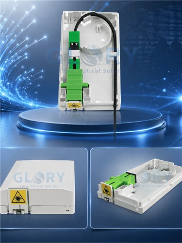
FDB, NAP box and termination box are not always the same
A fiber optic termination box is usually a smaller final connection point near the subscriber side. A fiber distribution box serves multiple drop cables at a distribution node. A NAP box is an outdoor network access point, often pole-mounted or wall-mounted, and usually designed with individually protected subscriber ports. These products all belong to the wider fiber box category, but the project position decides the right specification.
The 8 Selection Factors That Actually Matter

1. Port count and subscriber growth
Common FTTH boxes use 4, 8, 12, 16 or 24 ports. An 8-port fibre optical distribution box may fit a small residential access point, while 16-port units are common for outdoor distribution nodes and 24-port boxes fit MDU or FTTB areas. Select the port count from the subscriber plan plus spare ports for future activation. Oversizing should be deliberate, not automatic.
2. Splice capacity and splice tray layout
Port count and splice capacity are different. A 16-port adapter panel does not always mean the box can hold 16 or 24 fusion splices plus spare fibers and pigtails. For loaded boxes, the fiber optic pigtail length also affects internal routing. The RFQ should state both adapter count and splice capacity.
3. PLC splitter ratio and installation space
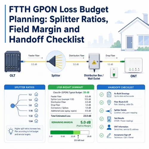
A distributed splitting design may place a PLC splitter inside each FDB. A 1×8 or 1×16 splitter is common in compact FTTH access nodes. A 1×32 splitter can be used only when the ODN loss budget allows it and the box has enough room for the splitter body, fan-out fibers and parking fibers. Use an FTTH ODN design guide or project loss-budget sheet before fixing the splitter ratio.
4. Adapter type and connector polish
SC/APC is common in FTTH because angled physical contact helps control back reflection in PON links. SC/UPC may appear in some legacy or local networks, but it should not be mixed with SC/APC in the same port path. Treat return loss and insertion loss as project values from the selected component datasheet, not as generic promises. For connector choices, see the Glory Optical guide to fiber optic connector types and specify the matching SC/APC fiber patch cord in the BOM.
5. IP rating and real sealing design
IP65 is often suitable for sheltered outdoor wall or pole locations. IP66, IP67 or IP68 may be required for stronger water exposure, ground-level positions, underground chambers or flood-prone sites. IEC 60529 defines the IP code system for protection against dust and water ingress. In practice, the box shell rating is only one part of the answer: cable gland size, rubber grommet fit, unused port caps and installation angle decide whether the unit stays dry.
6. Cable entry, cable diameter and strain relief
Feeder cable and drop cable diameters must be provided before production. A typical outdoor feeder cable may be much larger than a flat or round drop cable, so one universal gland cannot serve every entry. Strain relief should hold the cable jacket, not the fiber itself, so pulling force does not reach splices or adapters.
7. Bend-radius area and slack storage
ITU-T G.657 covers bend-insensitive single-mode fiber used in access networks, but bend-tolerant fiber still needs controlled routing. A well-designed FDB should provide slack storage and bend-radius control so a technician can rework one subscriber fiber without disturbing live ports.
8. Mounting method and accessories
Wall mounting, pole mounting, aerial mounting and cabinet installation require different brackets and hardware. A NAP fiber distribution box often needs pole straps or outdoor wall brackets, while an indoor MDU box may only need screws and a controlled-access cover. Include the mounting method in the RFQ, not only the box model.
Indoor vs Outdoor Fiber Distribution Box: What Changes in the Specification?
| Environment | Material and structure | Specification focus |
|---|---|---|
| Indoor MDU corridor | ABS or PC+ABS wall box | Clean access, splice tray, port label, compact size and installer safety. |
| Outdoor wall or pole | UV-resistant PC+ABS or SMC | IP rating, UV exposure, gasket quality, pole bracket and cable strain relief. |
| Public ground-level area | Reinforced polymer or metal enclosure | Impact resistance, lock type, security and maintenance access. |
| Cabinet installation | Compact inner distribution unit | Panel density, port map, cable routing and compatibility with cabinet space. |
Loaded vs Unloaded Fiber Distribution Box
A loaded fiber distribution box is factory-fitted with adapters, pigtails and sometimes a PLC splitter. It works well when the project uses a standard configuration across many sites and wants fewer field assembly steps. An unloaded fiber distribution box is better when field teams install different splitter ratios, adapter types or pigtail lengths at each node.
For ISP, contractor or distributor projects, define logo printing, neutral packaging, carton label, port map, accessory kit and batch test report before production. These items are inexpensive to specify early and difficult to correct after shipment.
How to Avoid Common Field Rework
The following review table is based on recurring FTTH box RFQ issues. It should be read as practical procurement guidance, not as a claim about every project or every supplier.
| Missing RFQ item | Field problem | Prevention |
|---|---|---|
| Feeder/drop cable diameter | Cable gland does not seal or cannot pass the cable. | List actual outer diameter range for every cable entry. |
| Splice capacity | Box has enough adapter ports but not enough splice positions. | State splice count, tray count and spare fiber requirement. |
| Splitter form factor | 1×16 or 1×32 splitter does not fit with the tray and adapters. | Specify steel-tube, ABS bare-block or plug-in splitter module. |
| Unused port sealing | Moisture enters through unsealed or loose ports. | Require port caps, grommets and gland configuration in the drawing. |
| Connector polish | SC/APC and SC/UPC are mixed, causing mismatch at the patch cord or ONT. | Lock adapter and patch cord polish in the BOM and port map. |
| Slack storage | Technicians disturb active fibers during maintenance. | Review internal routing area and minimum bend radius before order release. |
Standards and Documents to Request Before Order Release
External standards help define test methods and acceptance language, but they do not prove that a specific box has passed a specific test. Ask for the actual drawing, report, certificate or batch document for the product you are buying.
Fiber Distribution Box RFQ Checklist

| RFQ item | Why it matters | Example information |
|---|---|---|
| Port count | Defines subscriber capacity and spare ports. | 8, 16 or 24 SC/APC ports. |
| Splice capacity | Must support pigtails, distribution fibers and spare fibers. | 24 splices with two trays. |
| PLC splitter ratio | Affects internal space and ODN loss budget. | 1×8 or 1×16 ABS bare-block. |
| Adapter type | Prevents connector mismatch. | SC/APC simplex, all ports. |
| Loaded or unloaded | Defines factory assembly level. | Loaded with pigtails and splitter. |
| IP rating | Matches weather exposure. | IP65 for sheltered pole mount; IP67 if required by project. |
| Mounting method | Controls brackets and accessories. | Pole mount with stainless steel straps. |
| Feeder/drop cable diameter | Controls gland size and sealing. | Feeder 12 mm; drop cable 3×2 mm or 5 mm round. |
| Cable entry quantity | Prevents missing glands or blocked routes. | 2 feeder entries, 16 drop exits. |
| Labels and port map | Supports activation and maintenance. | Port 1–16 label plus A4 port map card. |
| OEM packaging | Supports ISP or distributor projects. | Neutral carton, logo label, accessory bag. |
| Test report | Supports project acceptance. | Batch insertion-loss report, end-face record if loaded. |
| Quantity and schedule | Controls production and logistics. | 500 units, delivery within six weeks. |
Example Specification Templates
Use these examples as RFQ formats, not as universal recommendations. Adjust each item to the actual ODN layout, operator requirement and cable schedule.
8-port FTTH access box
8 × SC/APC simplex, 12-splice tray, optional 1×8 splitter, IP65, wall or pole mounting, feeder gland range confirmed by cable OD, port caps for unused ports.
16-port outdoor FDB
16 × SC/APC simplex, 24-splice capacity, optional 1×16 PLC splitter, UV-resistant housing, IP65/IP66 project target, pole bracket, port map and batch test report.
24-port distribution box
24 × SC/APC simplex, multi-tray splice area, clear port numbering, wall/cabinet mounting, enough slack storage for maintenance and documented pigtail routing.
NAP configuration
Outdoor protected ports, lockable or capped subscriber access, pole/wall mounting kit, cable strain relief, unused port sealing and optional OEM carton label.
Final Recommendation
Choose the fiber distribution box after checking the ODN layout, not before. The right box is the one that matches subscriber count, splitter plan, splice capacity, cable diameter, IP exposure, mounting method and maintenance workflow. Before order release, request the mechanical drawing, cable-entry range, port map, packaging details and required test documents. That small amount of specification work prevents many avoidable site delays.
FAQ
-
Q: What is the difference between a fiber distribution box and a fiber termination box?
A: A fiber distribution box normally serves several subscribers in the distribution layer of an FTTH ODN, while a fiber termination box is usually the smaller final connection point near the subscriber premises. Some products overlap by region, so check installation position, port count and internal splice space.
Q: Is IP65 enough for an outdoor FTTH fiber distribution box?
A: IP65 can be suitable for sheltered outdoor wall or pole installations. For heavy rain exposure, high-pressure water, ground-level locations or flood-prone sites, IP66 or IP67 may be more appropriate. Real waterproof performance also depends on cable glands, grommets and unused port sealing.
Q: Can a fiber distribution box hold a PLC splitter?
A: Many FTTH fiber distribution boxes can hold a PLC splitter, but the form factor must match the internal layout. Check whether the box supports steel-tube, ABS bare-block or plug-in splitter modules, and make sure there is room for fan-out fibers, adapters and slack storage.
Q: What port count is best for FTTH projects?
A: There is no universal best port count. 8-port boxes often suit low-density drop points, 16-port boxes suit many outdoor FTTH access nodes, and 24-port or larger boxes fit MDU or FTTB locations. Select the port count from the subscriber plan plus spare capacity.
Should I order a loaded or unloaded fiber distribution box?
Choose a loaded box when adapter type, pigtail length and PLC splitter ratio are standardized across the project. Choose an unloaded box when field teams configure each node differently or when the buyer already controls adapters, pigtails and splitter inventory.Q: What information should I send before requesting a quotation?
A: Send port count, splice capacity, adapter type, splitter ratio, loaded or unloaded configuration, IP rating, installation environment, mounting method, feeder and drop cable diameter, cable entry quantity, pigtail length, labels, OEM packaging, test report needs, quantity and delivery schedule.
Q: What is the difference between a NAP box and a fiber distribution box?
A: A NAP box is a specific outdoor access point used near the last passive node before subscriber drop cables. A fiber distribution box is a broader category that can include NAP boxes, MDU corridor boxes, outdoor wall-mounted boxes and building entrance distribution boxes.
Q: Why is cable diameter important when choosing an FTTH distribution box?
A: Cable diameter decides whether the selected cable gland can seal and hold the cable correctly. If the gland is too large, water sealing may fail. If it is too small, the cable may not pass through or the jacket may be damaged during installation.