Match the fiber infrastructure to the way your racks are used. Explore five GLORY product options for conventional termination, high-density patching, rack-to-rack backbones and LC equipment connections.

GLORY 2U LGX MPO patch panel. Plan fiber capacity together with module access, cable routing and future expansion. View this rack-mounted MPO patch panel.
Start With the Rack Application
A rack must accommodate both today's connections and tomorrow's maintenance. A dense adapter field is useful only when technicians can identify the link, reach its connector and route the cable without straining adjacent connections.
GLORY's data center cabling portfolio includes rack-mounted fiber patch panels and MTP/MPO cable assemblies. Choose the panel around the termination method and available rack space, then match the trunk and equipment connections to the selected interfaces.
01
Terminate
Provide a defined location for incoming fiber, splices and adapters.
02
Distribute
Organize connections into accessible panels and modules.
03
Connect
Match the backbone and equipment-side fiber interfaces.
Which GLORY Product Fits Your Rack?
Use the comparison below to shortlist products. The quoted assembly should specify its actual loading, interfaces and cable configuration.
| Application | Recommended Product | Selection Basis | Confirm Before Ordering |
|---|---|---|---|
| Conventional rack termination | GL-JPF sliding patch panel | 19-inch, 1U/2U range | Adapter and splice configuration |
| Expansion with limited rack space | 1U LGX 96-fiber panel | Four 24-fiber modules | Cassette loading and service access |
| Centralized rack or row patching | 2U LGX MPO patch panel | Up to 192 fibers | Fiber count versus duplex connections |
| Multi-fiber backbone links | MPO-to-MPO trunk cable | Pre-terminated multi-fiber assembly | Polarity, gender, fiber type and length |
| MPO backbone to LC equipment | MPO-to-LC breakout cable | Individual LC branches | Branch count and equipment mapping |
Five GLORY Products for Practical Rack Cabling
The following recommendations cover the passive fiber layer, from incoming cable termination to equipment-side transitions.

GL-JPF Sliding Fiber Patch Panel
For incoming fiber termination in an enterprise server room, the GL-JPF series combines patching, splicing and fiber storage in a sliding enclosure. The range includes 1U and 2U models for 19-inch racks, with a series maximum of 48 fibers and SC, FC or ST adapter options depending on configuration.
The pull-out structure provides access to internal connections during installation and maintenance.
Configuration focus: Specify the exact model, adapter layout, splice capacity and whether pigtails and accessories are included.
Best for: Conventional fiber termination, server-room retrofits and projects that need accessible splice storage.

1U LGX 96-Fiber Patch Panel
When rack space is limited, the 1U LGX panel provides a modular option. Its listed configuration accommodates 96 fibers across four 24-fiber cassettes in a 19-inch frame, using a sliding tray.
The four-module arrangement lets project teams organize connections by equipment group and plan cassette loading around deployment phases.
Configuration focus: Confirm cassette compatibility, MTP input and LC or SC output configuration, and whether the quotation covers an empty enclosure or a loaded assembly.
Best for: Space-constrained racks and staged deployment of modular fiber connections.
2U LGX MPO Patch Panel
For a distribution point serving multiple racks, the 2U LGX MPO panel offers centralized modular patching. The product specification lists a 19-inch, 2U enclosure with a maximum capacity of 192 fibers and LC duplex front connectivity.
Modules can be organized around rack groups or services, while the enclosure provides a defined location for backbone termination and equipment-side patching.
Configuration focus: Verify the loaded cassette arrangement, rear cable routing and front service clearance. The 192-fiber rating is a fiber count, not 192 LC duplex connections.
Best for: Rack- and row-level aggregation with a larger number of fiber terminations.

MPO-to-MPO Trunk Cable
For multi-fiber links between racks or distribution areas, an MPO-to-MPO trunk connects compatible multi-fiber interfaces without individual field connectorization. GLORY lists this cable family with custom-length options.
Use it with a matching adapter panel or cassette system to establish a planned backbone route.
Configuration focus: Confirm fiber type, active fiber count, connector gender, polish, polarity, jacket and route length against the approved cable schedule. Select supported speed and reach from the transceiver specification and complete channel budget.
Best for: Preplanned panel-to-panel backbones and compatible multi-fiber equipment links.

MPO-to-LC Breakout Cable
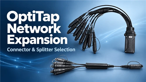
When the backbone uses an MPO interface and the equipment side needs LC connections, an MPO-to-LC assembly separates the multi-fiber connection into identifiable branches. The product image shown here has six LC duplex branches.
The branch layout can support equipment-level patching when its fiber map matches the required channel.
Configuration focus: Confirm the number of LC duplex branches, leg lengths, polarity and connector polish on the quotation. For transceiver breakout, also verify that the switch and optical module support the intended operating mode.
Best for: MPO-to-LC transitions and equipment connections with a defined branch map.
Need a coordinated configuration?
Plan the Panels and Cables Together
A project BOM should connect every panel, module and cable to its intended position in the channel.
- Equipment and transceiver interfaces
- Rack layout and available U space
- Fiber counts and route lengths
- Polarity and branch mapping
- Labeling and acceptance records
Explore the GLORY Data Center Fiber Cabling Solution for a configuration approach that connects these requirements.
Build the Complete Fiber Channel
A structured channel can use an MPO trunk between distribution points and a cassette to transition to duplex LC patching. Where the equipment interface requires it, an MPO-to-LC breakout provides individual branches. Choose the arrangement before ordering individual assemblies.
Panel and Module Configuration
Match the enclosure, cassette format and front/rear interfaces. Reserve space for pulling the tray, opening the module and reaching connectors. Compare the GLORY fiber patch panel range by these requirements.
Trunk and Equipment Configuration
Define active fibers, connector gender, polish, polarity and length for each assembly. Include every connection in the loss budget, then select from the MTP/MPO trunk and breakout range.
What to Include in Your Project Request
Prepare the following inputs so the quotation identifies the required assembly rather than only a product family.
Rack and Panel Requirements
- Rack width, available U space and mounting depth
- Initial and planned fiber counts
- Adapter type and cassette arrangement
- Empty or loaded enclosure
- Splicing accessories and cable-entry requirements
Cable and Documentation Requirements
- Fiber type, fiber count and route length
- Connector type, gender, polish and polarity
- Breakout count and branch lengths
- Jacket, labels and packaging
- Required optical tests and report format
For project-specific lengths, connector combinations, identification or packaging, review GLORY's OEM/ODM fiber cabling customization options. Agree the final configuration and documentation requirements before production.
Frequently Asked Questions
Should I choose a conventional panel or an LGX panel?
Choose around the termination method. A conventional sliding panel can suit incoming cable splicing and adapter-based patching. An LGX panel is useful when the design calls for compatible modular cassettes. Start with the application comparison, then confirm the internal configuration.
Does 192 fibers mean 192 LC duplex connections?
No. A conventional LC duplex connection uses two fibers. A fully populated 192-fiber arrangement could therefore represent 96 duplex pairs, provided the specified panel and modules implement that layout. Confirm the populated BOM.
How do I choose an MPO-to-LC branch count?
Use the equipment interface and fiber map. A 12-fiber assembly can provide six conventional duplex pairs when all fibers are used that way; other applications may use a different allocation. The pictured breakout has six LC duplex branches. Confirm the ordered branch count explicitly.
Can the same cable support every 400G or 800G interface?
No. Select fiber type, connector format, active fibers and polarity for the actual transceiver and channel. GLORY's data center fiber configuration approach starts with the equipment interface.
Can GLORY supply project-specific cable configurations?
GLORY lists customization options for cable length, connectors, labeling and packaging. Review the OEM/ODM options and request a configuration-based quotation for your project.
Related GLORY Resources
- Data Center Cabling Products - browse the overall passive fiber portfolio.
- Fiber Optic Patch Panels - compare enclosure and distribution options.
- MTP/MPO Cable Assemblies - explore trunks and equipment transitions.
- Data Center Fiber Cabling Solution - coordinate the channel and documentation.
Configure Your GLORY Rack Cabling Solution
Send your rack layout, equipment list, required fiber counts and cable routes to GLORY. Use these inputs to define the panel, module and cable combination for your installation.