

GL-A7-32 32-Core Fiber Optic Distribution Box
The GL-A7-32 fiber optic distribution box provides a 32-core feeder-to-drop termination point for FTTx access networks. Its 290 × 210 × 111 mm PC+ABS enclosure combines cable fixation, splice protection, fiber storage and distribution, with a flip-up panel for internal access and a stated IP65/66 protection designation. Select the wall or pole installation package and confirm the GL-A7-32R/T variant, optical loading and cable-entry sealing for the intended building or outdoor node.
|
|
32-Core Capacity with Flip-Up Internal AccessProduct line: FTTx Fiber Distribution / Termination Boxes Bring feeder and customer fibers together in a housing with separate routing paths and an accessible internal panel. Capacity: 32 fibers · Housing: 290 × 210 × 111 mm · Mounting: wall / pole |

Housing, Cable Entry and Panel Access
|
|
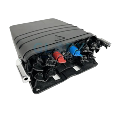
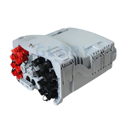
A Cable-Entry Face to Match the Feeder and DropsThe entry-side photograph shows the enclosure's cable-access layout. Match each cable construction to its sealing component and fixing point before assigning fibers. The listed 12 mm joint aperture and 16 mm tapping-plug opening are entry dimensions; the cable outside diameter and seal working range should be agreed for the selected parts. |

|
|
Separate Fiber Routing Around the Internal PanelWith the lid open, the internal panel provides an organized location for the selected optical components. Use a loading drawing to identify splice positions, any splitter assembly and the fiber path to the outputs. Specify adapter type, component quantities and reserve-fiber allowance for the actual 32-core arrangement. |

|
|
Flip the Panel to Reach the Cable-Fixing AreaThe raised-panel view exposes the lower fixing area. This access arrangement helps separate cable preparation from the fiber-management work above it. Confirm the panel travel and lead routing with the intended loading so a technician can reach the lower compartment while retaining an orderly fiber path. |

Colour confirmation: the configuration table specifies black; the photographs illustrate a light-coloured sample. Confirm the supply colour with the approved sample or order drawing.
What to Specify for a 32-Core Distribution Point
Define the Fiber Allocation
The declared capacity is 32 cores. Build the connection schedule around incoming fibers, splices and customer drops, then choose the adapters and splitter loading required by that circuit. Keeping the fiber allocation explicit gives procurement and installation teams the same reference when agreeing the populated assembly.
Keep Cable Restraint with the Cable Preparation
Feeder and drop clamping are integrated with the splicing, fixation, storage and distribution functions. Establish the jacket-fixing and fiber-transition positions on the loading drawing. This lets the installer prepare the cable at its fixing point before routing the exposed fibers through the internal guides.
Plan Access Through the Flip-Up Panel
The flip-up panel separates access to the internal work areas. Allow room for the panel to move with the chosen leads and reserve fiber in place. A sample loaded to the intended configuration can be used to review the opening sequence and routing before batch assembly.
Set the Enclosure Protection Requirement
The PC+ABS housing has a stated IP65/66 designation and a fully enclosed structure. Agree the required grade with the cable seals, plugs and mounting parts that will be delivered. Include the assembled configuration and acceptance evidence in the project specification for exposed FTTx locations.
Order the Mounting and Shipping Package Together
Wall and pole versions share the 290 × 210 × 111 mm housing but use different packing dimensions and weights. Select the installation kit before planning deliveries. Each outer carton is listed at 10 pieces, allowing the site allocation to be checked against carton quantities and handling weights.
GL-A7-32 Fiber Optic Distribution Box Specifications
|
Item |
Specification |
|---|---|
|
Product family |
FTTx fiber optic distribution / termination box |
|
Product references |
GL-A7-32; GL-A7-32R/T - confirm the ordered variant |
|
Declared enclosure protection |
IP65/66 - confirm the required grade for the assembled configuration |
|
Enclosure material |
PC+ABS (configuration table: PC/ABS) |
|
Enclosure functions |
Feeder/drop cable clamping; fiber splicing, fixation, storage, splitting and distribution |
|
Internal access |
Flip-up panel with separate cable-management pathways |
|
Installation arrangements |
Wall and pole kits; messenger-wire installation illustrated |
|
Configuration item |
Wall mounting |
Pole mounting installation |
|---|---|---|
|
Fiber capacity |
32 core |
32 core |
|
Size(mm) |
290*210*111 |
290*210*111 |
|
Material |
PC/ABS |
PC/ABS |
|
Color |
black |
black |
The 32-core designation describes fiber capacity. Agree the adapter positions, splice loading, connector interface and splitter circuit on the order drawing. The suffixes R/T should be confirmed for the selected assembly.
Packing Dimensions, Weights and Entry Openings
|
Packing item |
Wall mounting |
Pole mounting |
|---|---|---|
|
Inner box size(mm) |
300*220*115 |
300*220*125 |
|
Individual weight(kg) |
1.5 |
1.6 |
|
Outer box size(mm) |
600*310*460 |
650*310*460 |
|
Gross weight(kg) |
15.9 |
16.9 |
|
Outer box capacity(PCS) |
10 |
10 |
|
Entry component dimension |
Wall mounting |
Pole mounting |
|---|---|---|
|
Waterproof joint aperture (mm) |
12 |
12 |
|
Tapping-plug hole diameter (mm) |
16 |
16 |
Both installation packages list a 12 mm waterproof-joint aperture and a 16 mm tapping-plug hole. Confirm seal sizes and the permitted cable diameter against the selected entry component. For logistics, use the individual and gross weights with their corresponding inner and outer cartons.
FTTx Distribution Box Applications
32-Core FTTH Distribution at a Building Entry
A building entry can become difficult to trace when feeder fibers, customer drops and spare fiber are left without a defined allocation. Place the GL-A7-32 at the agreed distribution point and use its 32-core capacity to prepare a numbered splice and output schedule. The flip-up panel and routing paths provide a structure for the selected pigtails, adapters and any splitter assembly. Before purchasing, confirm the wall fixing surface, optical component list, cable seals and the space needed to open the cover and panel during later subscriber work.
Pole Distribution for a Group of Subscriber Drops
On a pole route, enclosure selection also determines how cables are restrained and how the installer reaches the fiber work. Use the GL-A7-32 pole package at a planned feeder-to-drop node, with the support fittings and cable approach shown on the installation drawing. Its enclosed PC+ABS body and stated IP65/66 designation provide the starting specification for the required protection review. Confirm the support dimensions, bracket set, customer-drop construction and seal working ranges. The pole version has its own carton sizes and listed weights, which should follow the site delivery schedule.
Phased FTTx Builds with Repeated Distribution Nodes
For a phased access build, sending every site an enclosure without a mounting and optical schedule can leave the correct parts in the wrong shipment. Specify the GL-A7-32 by node, identifying the 32-core fiber allocation, internal loading and installation kit for each location. Use the separate wall and pole packing figures to prepare the dispatch list, and plan around the stated 10-piece outer-carton quantity. Where an aerial position calls for messenger-wire suspension, review the illustrated method and agree the actual suspension hardware, cable support and access requirements before release.
Installation Methods and Site Preparation
|
|
Wall InstallationUse the wall arrangement at the specified building entry, corridor or equipment-room position. Check the fixing pattern and substrate, and leave room above the enclosure for the cover and flip-up panel to open. Confirm the bracket drawing for the ordered GL-A7-32 variant. |

|
|
Pole InstallationChoose the support fittings to suit the pole geometry and the planned cable approach. Record the bracket parts, restraint points and installation instructions with the node drawing. Confirm that the supplied pole kit and entry seals match the assembly on the purchase order. |

|
|
Messenger-Wire InstallationFor a suspended location, define the messenger wire, clasp arrangement and cable support with the route designer. Request the hardware dimensions and load information for that installation. The method illustration helps communicate the attachment arrangement; use an approved drawing to identify the supplied components. |

Transport and Storage Before Installation
|
Handling condition |
Specified limit |
|---|---|
|
Transport temperature |
−35°C to +55°C |
|
Storage temperature |
−5°C to +45°C |
|
Storage relative humidity |
<70% |
Keep accessories in their sealed bags and follow the carton handling marks. Protect uninstalled units from heavy rain; handle the cartons carefully, keeping them upright and avoiding rolling or impact. Store them in a controlled area away from corrosive gases.
These are transport and storage limits. Request the operating and installation temperature requirements for the intended deployment when preparing the final specification.
Ordering Information for the GL-A7-32
|
Order item |
Details to confirm |
|---|---|
|
Variant and colour |
Confirm GL-A7-32 / GL-A7-32R/T reference, required colour and approved assembly drawing |
|
Optical loading |
32-core allocation; splice and adapter quantities; connector interface; splitter package and ratio if fitted |
|
Cable entry |
Feeder/drop cable construction, actual outside diameters, seals, plugs and fixing components |
|
Installation kit |
Wall, pole or agreed messenger-wire arrangement; bracket / suspension drawing and hardware list |
|
Inspection and delivery |
Required protection grade, sample review, labels, quantity by kit and carton allocation |
Send the fiber schedule, cable details and mounting drawing with your inquiry. Glory Optical can review the GL-A7-32 assembly, component selection and project labeling and packing requirements against that information.
Explore Fiber Optic Termination Boxes
About Glory Optical
|
Glory Optical facility, Ningbo |
Glory OpticalFounded in 2008 · Ningbo, China · OEM/ODM support Ningbo Glory Optical Communication Co., Ltd. manufactures passive fiber optic products and supplies telecom operators, ISPs, contractors, distributors and OEM/ODM buyers. Our portfolio covers fiber boxes, splice closures, PLC splitters, fiber optic cables, patch cords, pigtails, adapters, MTP/MPO assemblies and installation accessories for fiber network projects. Manufacturing & OEM/ODM SupportManufacturing capabilities across our product families include mold development, enclosure molding, component assembly and fiber cable assembly. OEM/ODM projects can cover drawings, product configuration, samples, branding, labels and packaging, according to the selected product and confirmed requirements. |

Testing Capabilities
Glory Optical supports inspection and testing according to confirmed product specifications and order requirements. The following videos show examples from our testing activities.
Water Spray Testing |
Sealing Performance Testing |
Water Resistance Testing |
Specification Review & Project Documentation
Before batch production, confirm the drawing or sample, product configuration, inspection requirements and packing details. For connectorized products, applicable inspection can include insertion loss, return loss and connector end-face checks. Datasheets, drawings and applicable test documents can be discussed for the order.
Discuss Your Product or Project Requirement
Send the product model, quantity, application and required configuration for quotation or sample discussion. Include any drawing, labeling, packaging and documentation requirements so our team can review the order details.
Email: sales@gloryoptic.com
Hot Tags: ip65 fiber optic distribution box, China ip65 fiber optic distribution box manufacturers, suppliers, factory, 24 Port Fiber Termination Box, box fiber, fiber closure box, fiber optic termination box, Nid Box, outdoor fiber distribution box