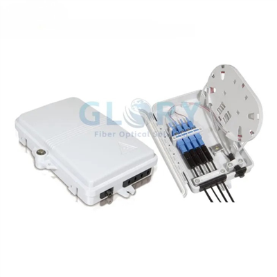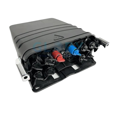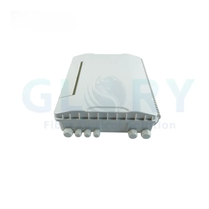

GL-KSW-48A FTTH Splitter Distribution Box Overview
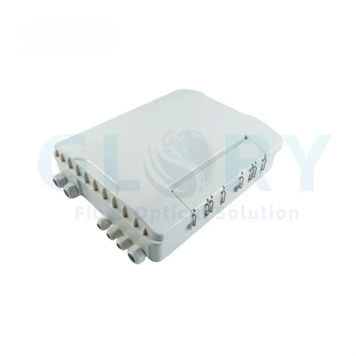
The GL-KSW-48A is a high-capacity access-network enclosure for introducing and fixing feeder or distribution cables, organizing stripped fibers, protecting fusion splices, storing pigtails and patch cords, and presenting up to 48 adapter interfaces for downstream connections. The internal layout combines splice-tray storage with a modular patching area so fiber capacity, adapter capacity and drop-port quantity can be reviewed separately during BOM confirmation.
The original product page identifies SC or FC adapter loading, 48 drop-cable positions, top and bottom cable access, pole or wall mounting and a buckle-type closure. It does not identify the enclosure material, connector polish, fiber standard, cable-diameter range, PLC splitter ratio, optical insertion loss or return loss. Those items are therefore project selections rather than default specifications on this page.

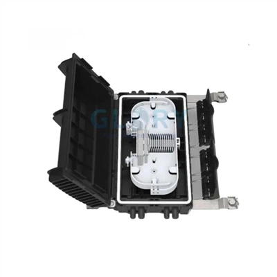
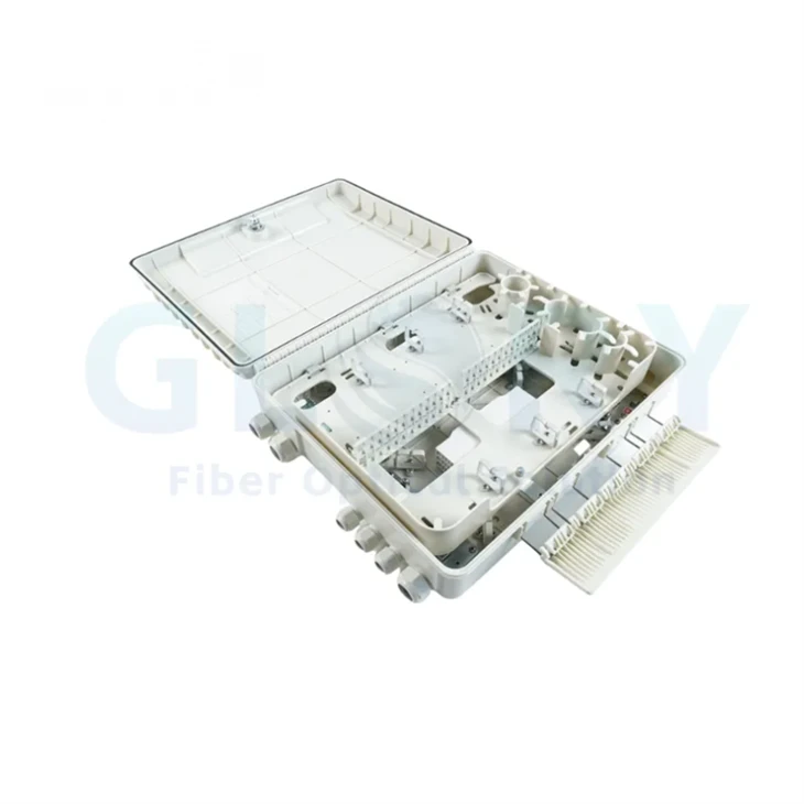
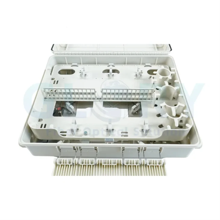
Open enclosure view showing splice-management, cable-routing and adapter-patching areas.
Technical Selling Points of the 48-Port FTTH Splitter Distribution Box
48 SC or FC Adapter Positions
The modular patching area accepts 48 SC or FC adapters, allowing procurement teams to select the interface family that matches the existing ODN. Keeping adapter capacity separate from splice capacity prevents a 48-port requirement from being mistaken for a 48-fiber internal splice limit and simplifies port-map review before assembly.
Up to 96 Fibers of Splice Storage
Each stated splice tray holds 24 fibers, while the enclosure has a stated maximum splice capacity of 96 fibers. This gives the box reserve for feeder branching, restoration fibers or staged subscriber activation without forcing every managed fiber to terminate on an adapter during the first deployment phase.
12 Cable Entrance Ports with Top and Bottom Access
Twelve physical cable entrance ports support routing from both the upper and lower sides of the enclosure. Compared with a single-direction entry layout, this allows the approved port map to follow pole, wall or duct approach direction, reducing unnecessary cable crossover inside the housing. Cable diameters must be confirmed before ordering.
Separated Splicing, Patching and Fiber Storage
The enclosure is designed to introduce, fix and strip optical cable, protect fusion splices, store pigtails and patch cords, and present a modular adapter field. Separating these functions gives technicians a defined route for incoming fibers and subscriber-side connections, while buyers can specify loaded or unloaded assemblies against a drawing.
IP55 Environmental Protection Range
The stated IP55 rating, −40°C to +60°C operating range and 70–106 kPa atmospheric-pressure range define the published environmental envelope. A buckle-type closure and protected lock area secure the cover. IP55 should be matched to the actual exposure level and must not be interpreted as approval for continuous immersion or an underground handhole that can flood.
Wall or Pole Mounting with Listed Hardware
The product page lists wall- and pole-mounted deployment and provides a defined wall-mounting hardware set. This gives project teams a documented accessory baseline rather than relying on improvised fasteners. Pole straps, brackets, cable clamps and site-specific corrosion requirements should still be identified in the RFQ and installation drawing.
GL-KSW-48A Product Family and Configuration Options
GL-KSW-48A
The original product heading and model table identify GL-KSW-48A. Some later source-page sentences and the packaging paragraph use GF-KSW-48A. The purchase order, label artwork, drawing and carton mark should use one approved model designation before production.
- 48 SC or FC adapter positions
- 24 fibers per splice tray
- 96-fiber maximum splice capacity
- 48 stated drop-cable positions
- 12 cable entrance ports

General Technical Specifications for the FTTH Splitter Distribution Box
General Technical Specifications
| Parameter | Published Specification | Procurement Note |
|---|---|---|
| Product model | GL-KSW-48A | GF-KSW-48A also appears in source-page prose; approve one model mark. |
| Product family | FTTH splitter distribution box / fiber optic termination box | Used for cable termination, splicing, patching, branching and protection. |
| Dimensions | 504 (L) × 374 (W) × 134 (H) mm | Confirm mounting-hole and clearance drawing. |
| Weight | 4.8–5.2 kg | Published range; loaded configuration may affect final shipment weight. |
| Cable entrance ports | 12 | Top and bottom entry are stated; cable diameter is not published. |
| Splice tray capacity | 24 fibers per tray | Number of installed trays should be confirmed. |
| Maximum splice capacity | 96 fibers | Splice capacity is not the same as adapter capacity. |
| Adapter capacity | 48 SC or FC adapters | Connector polish and simplex/duplex format are not stated. |
| Drop-cable capacity | 48 pieces | Drop-cable profile and diameter require drawing confirmation. |
| IP rating | IP55 | Not a continuous-immersion rating. |
| Operating temperature | −40°C to +60°C | Installation and storage temperatures are not separately stated. |
| Atmospheric pressure | 70–106 kPa | Published environmental condition. |
| Mounting method | Wall mounting or pole mounting | Confirm required brackets, straps and fasteners. |
| Closure structure | Buckle-type structure with protected lock area | Detailed gasket material and sealing-test method are not stated. |
| Enclosure material | Not stated on the source page | Specify material, color and UV requirement in the RFQ. |
Model and Capacity Table
| Model | Adapter Positions | Splice Tray Capacity | Maximum Splice Capacity | Cable Entries | Drop Positions | Dimensions |
|---|---|---|---|---|---|---|
| GL-KSW-48A | 48 × SC or FC | 24F per tray | 96F | 12 | 48 | 504 × 374 × 134 mm |
Splitter Configuration Status
| Splitter Item | Source-Page Status | Required RFQ Confirmation |
|---|---|---|
| PLC splitter ratio | Not stated | Specify required ratio and architecture. |
| Input / output count | Not stated | Confirm feeder inputs, branch outputs and spare ports. |
| Splitter package | Not stated | Specify bare, steel tube, ABS module, cassette or project drawing. |
| Connector type / polish | SC or FC adapter families stated; polish not stated | Confirm SC/APC, SC/UPC, FC/APC or FC/UPC as applicable. |
| Insertion loss, uniformity, PDL and directivity | Not published for this product configuration | Set acceptance limits and request a test report for loaded assemblies. |
| Loaded or unloaded supply | Not defined | Confirm whether adapters, pigtails, splitters and splice sleeves are factory installed. |
Cable and Connector Compatibility
| Interface Area | Published Information | What Must Be Confirmed |
|---|---|---|
| Feeder / distribution cable entry | 12 entrance ports; top and bottom access | Cable count per port, outside diameter, sheath type and strength-member fixing. |
| Source-page cable-loading statement | Described as handling 10–15 distribution cables and eight figure-3 soft cables | This description does not map directly to the 12 entrance ports; request an approved port-layout drawing. |
| Adapter interface | 48 SC or FC adapters | Polish type, sleeve material, dust-cap style and adapter color. |
| Drop-cable exits | 48 pieces | Flat or round cable profile, diameter, sealing insert and retention method. |
| Fiber type | Not stated | Confirm G.652.D, G.657.A1/A2 or project-specific fiber. |
| Optical acceptance | No connector, splice or splitter loss values published | Define whether limits apply to a single component, mated pair, splitter port or end-to-end assembly. |
FTTH Splitter Distribution Box Applications and Access-Network Solutions
48-Port FTTH Last-Mile Distribution at Building or Street Nodes
A small terminal selected only by subscriber count can run out of splice storage when feeder branching, reserve fibers and restoration loops are added. The GL-KSW-48A separates 48 adapter positions from a stated 96-fiber maximum splice capacity, allowing it to serve as a wall- or pole-mounted distribution point between feeder cable and downstream drop routes. It can interface through SC or FC adapters to patch cords, pigtails and subscriber-side distribution cables. Before procurement, confirm the active port count, spare-fiber policy, cable entry drawing and whether the enclosure is supplied loaded or unloaded.
GPON or XGS-PON Splitter Integration Point
Ordering a "splitter box" without defining the split architecture can produce the wrong number of inputs, outputs or connectorized ports. This enclosure provides the splice, storage and adapter space needed for a project-specified PLC splitter assembly, but the original page does not assign a standard ratio or optical-loss limit. It can be installed at an FTTH distribution node downstream of the feeder network and upstream of building or subscriber drops. The RFQ should state the PON class, split ratio, connector polish, splitter package, fiber type, output-port map and required test-report format.
Pole- or Wall-Mounted Outdoor Distribution Routes
Improvised mounting and cable approach direction can force sharp internal turns or expose entry seals to unnecessary strain. The GL-KSW-48A provides 12 cable entrance ports, stated top and bottom access, an IP55 enclosure and wall- or pole-mounting options, allowing the port map to follow the planned feeder and drop directions. It suits outdoor FTTH/FTTx distribution points where IP55 matches the site assessment. Buyers should confirm pole diameter, bracket or strap material, cable outside diameter, UV exposure, grounding requirements and whether the location may flood or require a higher ingress rating.
MDU, Campus and Enterprise Access Distribution
In multi-building or multi-tenant networks, using one capacity number for every function can lead to insufficient splice storage or excessive adapter loading. The GL-KSW-48A combines 48 SC or FC adapter positions with up to 96 fibers of stated splice capacity, supporting phased activation from a central wall-mounted distribution point in an MDU service area, campus utility zone or enterprise access network. It can connect feeder, riser, distribution and drop segments through project-selected pigtails and patch cords. Confirm tenancy or building port labels, reserved fibers, connector family, splitter use and maintenance-access clearance before approval.
Selection Guidance
Separate Adapter, Splice and Drop Capacity
Do not use "48 port" as a substitute for every internal capacity. Confirm the required adapter quantity, live drops, reserve ports, fibers per tray and total splice count independently. The published combination is 48 adapter positions, 48 drop positions, 24 fibers per tray and 96 fibers maximum splice capacity.
Approve the Cable-Entry Drawing
The source page lists 12 physical entrance ports but also contains a separate cable-loading description that does not clearly map to those ports. Provide cable quantities, outside diameters, route direction and strength-member details, then approve a numbered entry and exit drawing before production.
Match IP55 to the Installation Environment
IP55 supports dust and water-jet resistance under the rating conditions, but it does not establish continuous underwater operation. For underground handholes, flood-prone sites, direct burial or more severe exposure, specify the required ingress test and select an enclosure designed for that condition.
Verify Model Marking and Packing Data
The original page alternates between GL-KSW-48A and GF-KSW-48A. Confirm the final nameplate, carton label and documents. Published packaging is one unit in a 550 × 405 × 160 mm inner carton and three units in a 565 × 420 × 540 mm outer carton.
Ordering Configuration
| Ordering Item | Available or Published Basis | Information to Put in the PO / BOM |
|---|---|---|
| Model designation | GL-KSW-48A; GF-KSW-48A also appears on source page | Approved model, revision and label artwork. |
| Adapter configuration | Up to 48 SC or FC | Quantity, connector family, polish, color and dust caps. |
| Splice configuration | 24F per tray; 96F maximum | Tray count, sleeve holder format and reserve fibers. |
| Splitter configuration | No default ratio published | Ratio, inputs, outputs, package, fiber type, connectorization and loss limits. |
| Cable interface | 12 entrance ports; 48 stated drop positions | Cable profile, OD, quantity, port map, sealing insert and retention. |
| Mounting | Wall or pole | Bracket, straps, fasteners, pole diameter and corrosion environment. |
| Branding | Custom logo stated on source page | Logo file, label language, port numbering and carton marks. |
| Packaging | Inner: 550 × 405 × 160 mm, 1 pc; outer: 565 × 420 × 540 mm, 3 pcs | Confirm export marks, pallet rules and accessory bag list. |
OEM and Project-Based FTTH Splitter Distribution Box Supply
Drawing and Port-Map Confirmation
Glory Optical's official company page states that project review can cover port count, fiber count, splitter ratio, loaded or unloaded construction, adapter type, splice-tray capacity, cable diameter, cable entry, mounting method, IP rating, labeling and port maps before quotation.
Housing, Assembly and Loaded Configuration
The company describes mold and CNC capability for enclosure geometry and port details, plus assembly of fiber boxes, splice trays, adapters, pigtails and cable-management parts against confirmed drawings. For this model, any material, splitter or connector configuration not published on the product page requires written approval.
Testing and Project Documentation
For connectorized products, the company page states that support may include insertion-loss, return-loss and end-face checks where applicable. Buyers can request datasheets, drawings, test reports, packing photos, product labels and applicable declarations, with final documentation defined by the approved order configuration.
Why Glory Optical for GL-KSW-48A Project Supply
Glory Optical Communication is a Ningbo-based manufacturer focused on passive FTTH and ODN infrastructure. For termination-box projects, the relevant capabilities include enclosure molding and dimensional control, assembly of boxes, splice trays, adapters and pigtails, PLC splitter integration, cable-management layout confirmation and packing against an approved BOM.
Project support can include drawing review, sample planning, port configuration checks, labeling, packing photos and applicable documentation. For connectorized or splitter-loaded assemblies, optical testing support may include insertion loss, return loss and end-face inspection where those requirements are included in the confirmed specification.


Our Quality Promise
Comprehensive 3-Year Warranty
We confidently back all our products with a 3-year warranty. Our specific service policy is: within one year for quality issues, we take full responsibility for returns; within two years, for replacements; and within three years, for repairs.
Clear & Competitive MOQ
We welcome both trial and bulk orders. Our standard Minimum Order Quantity (MOQ) is 50 units. We also offer free samples for testing to help you evaluate our quality with confidence.
Fast & Reliable Logistics
We guarantee delivery within 10 days for standard items. Our logistics advantage includes cost-effective door-to-door service to simplify shipping for you.
Our Foundation
Backed by 18 years of experience since 2008, we control quality from our own factory, accept OEM/ODM requests, and maintain ready stock for wholesale. We focus on delivering the optimal balance of price and quality directly to end customers worldwide.
Your trust is our priority. Partner with us for dependable fiber optic solutions supported by clear promises.
Hot Tags: ftth splitter distribution box, China ftth splitter distribution box manufacturers, suppliers, factory, 24 Port Fiber Termination Box, box fiber, Fiber Access Terminal Box, fiber breakout box, fiber cable termination box, fiber splice box