

GL-A3-8R Fiber Distribution Enclosure
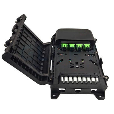
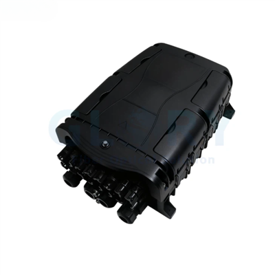
The GL-A3-8R brings eight-port fiber distribution, splice storage and micro PLC splitter installation into a 290 × 210 × 82 mm enclosure. Feeder and drop cables have dedicated clamping provisions inside the sealed PC+ABS body. For FTTx projects requiring an eight-fiber termination configuration, select wall or pole mounting, or discuss a messenger-wire suspension arrangement. Specify the installation kit, optical circuit and required IP65/66 protection conditions together.
|
|
An Eight-Connection Node with Splitter ProvisionGL-A3-8R · PC+ABS enclosure · Black finish Cable clamping, splice fixation, slack storage and distribution in one housing. Micro PLC splitter mounting provision; confirm module dimensions, split ratio and optical components for the ordered configuration. |

Plan the Fiber Work Inside the Box
Hold the Cables Before Managing the Fibers
Clamps for feeder and drop cables provide the mechanical fixing points at the cable transition. Identify the cable jacket and any strength-member attachment before arranging exposed fibers. The purchasing drawing should show which parts carry cable load and how the fibers reach their splice or termination positions.
Allocate Space for a Micro PLC Assembly
Plan the micro PLC splitter package and circuit around the local distribution point. Check module dimensions, mounting space and lead routing before selecting the optical assembly. Specify the split ratio and supplied components separately from the enclosure's eight-port capacity.
Keep Splices, Reserve Fiber and Outputs Traceable
Splicing, fixation, storage and distribution are the stated functions of this model. Assign each feeder fiber to its splice, splitter path or outgoing connection on a circuit schedule. Reserve fiber should remain identifiable when a technician accesses the box for a later customer connection.
Match the Seal to the Assembled Configuration
The supplied protection entry is IP65/66. Establish the required grade for the selected kit and cable population, including closure parts and unused entries. The PC+ABS body and water/dust-resistance description should be assessed as the complete delivered assembly.
Select Access That Suits the Route
Wall, pole and messenger-wire methods address different attachment points. Consider the working position needed to open the cover, reach the internal modules and support the cables. The installation hardware should be identified before the enclosure is allocated to a site.
Mounting Arrangements and Access Space
Choose wall, pole or messenger-wire installation to suit the cable route and available working space. The illustrations show mounting approaches; confirm bracket dimensions and fixing points against the GL-A3-8R drawing. For wall options A and B, request the drawing for the selected variant.
|
|
Wall: Select the A or B Fixing VariantOn a basement, corridor or equipment-room wall, position the unit so the lid travel and cable approach remain accessible. Name the required A/B mounting variant and the fixing pattern on the site drawing. The supplied wall kit has its own packing depth and weight, shown below. |

|
|
Pole: Check the Clamp and Support GeometryFor a pole location, define the support shape, attachment dimensions and cable restraint points. The illustrated mounting method uses a banded pole clamp; agree the actual kit and tightening procedure for the selected support. Confirm how the feeder and drops are supported independently of the internal fiber routing. |

|
|
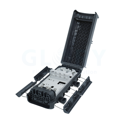
Messenger Wire: Confirm the Suspension HardwareThe aerial illustration shows suspension clasps attached to a messenger wire. Specify the clasp, attachment points and cable approach as part of the aerial installation design. Keep working access clear of the suspension hardware, and request the hardware load ratings for the planned installation. |

Wall Kit and Pole Kit: Packing Differences
|
Configuration item |
Wall mounting |
Pole mounting installation |
|---|---|---|
|
Specified termination count |
8 core |
8 core |
|
Size(mm) |
290*210*82 |
290*210*82 |
|
Material |
PC/ABS |
PC/ABS |
|
Color |
black |
black |
|
Inner box size(mm) |
300*220*95 |
300*220*115 |
|
Individual weight(kg) |
1.3 |
1.4 |
Both entries use the same listed housing dimensions. The wall package is 300 × 220 × 95 mm at 1.3 kg; the pole package is 300 × 220 × 115 mm at 1.4 kg. Keep the kit identity on shipping labels, and confirm whether the quoted individual weight includes the supplied accessories.
Environmental, Optical and Insulation Values
|
Item |
Declared value |
|---|---|
|
Operating temperature |
-40°C to +85°C |
|
Relative humidity |
≤85% at 30°C |
|
Atmospheric pressure |
70 kPa to 106 kPa |
|
Insertion loss |
≤0.15 dB |
|
UPC return loss |
≥50 dB |
|
APC return loss |
≥60 dB |
|
Insulation resistance |
≥2×10⁴ MΩ at 500 V DC |
|
Withstand voltage |
≥3000 V DC for 1 minute |
The insertion-loss entry has no stated wavelength or reference plane. Request the test setup and the applicable optical path for the ordered loading. UPC and APC are given separate return-loss thresholds; specify the actual connector family and polish in the component schedule.
For insulation and withstand-voltage testing, define the test points, assembly state and acceptance record. Include these details in the inspection plan for the ordered passive enclosure.
Additional Housing and Material Data
|
Parameter |
Specification |
Test / material reference |
|---|---|---|
|
Operating Temperature Range |
-40°C to +85°C |
IEC 60068-2-1 |
|
Storage Temperature Range |
-35°C to +55°C |
IEC 60068-2-2 |
|
Protection Rating |
IP65/66 |
IEC 60529 |
|
Connection capacity (listed ports) |
8 ports |
Industry Standard |
|
Material Composition |
PC+ABS Composite |
UL94 V-0 |
Keep operation and storage requirements separate: the supplied ranges are −40°C to +85°C and −35°C to +55°C respectively. Confirm the intended storage condition and product coverage before the specification is released for the project.
For temperature qualification, define the test programme and edition: IEC 60068-2-1 addresses cold testing and IEC 60068-2-2 addresses dry heat. Request evidence covering the required conditions. For the UL94 V-0 reference, confirm the resin grade, tested thickness and supporting material documentation; review finished-enclosure test requirements separately.
Choosing the GL-A3-8R for a Build
A Small Subscriber Cluster with a Local Split
Where the route design calls for a small group of drops at one accessible location, decide whether a micro PLC belongs inside the terminal or at an upstream point. For an internal split, provide the splitter package, ratio, input assignment and output schedule. Check the eight-port enclosure requirement against the actual number of populated customer connections. This model can then be specified around its clamps, splice protection and reserve-fiber arrangement, rather than around an assumed splitter count.
Repeated Nodes Along a Wall-and-Pole Route
A mixed route may use identical enclosure bodies with different installation kits. The GL-A3-8R packing data distinguishes wall and pole versions, which helps procurement separate the hardware even when the listed outer dimensions match. Create a site-by-site kit schedule, add the A/B wall variant where needed and identify any messenger-wire locations separately. Agree the mounting drawing before ordering, so the installer receives the appropriate attachments for each access point.
Acceptance Checks Before a Rollout
Use the supplied environmental, optical and insulation entries to prepare an acceptance schedule for the selected assembly. Resolve the IP65/66 designation, preserve the distinction between operation and storage conditions and identify the path used for insertion-loss testing. Where the purchase specification calls for electrical insulation tests, define the electrodes and assembly condition. Keep these records with the approved component list so the production inspection can be tied to the exact delivered configuration.
Prepare the Configuration Request
|
Decision to supply |
Information for the quotation |
|---|---|
|
Fiber circuit |
Eight-port requirement, numbered fibers, splice plan and micro PLC package / ratio if fitted |
|
Cable fixing |
Feeder and drop constructions, clamp parts, entry seals and reserve-fiber route |
|
Installation package |
Wall A/B, pole or messenger-wire arrangement; mounting drawing and accessory list |
|
Evidence for acceptance |
Selected IP grade, temperature coverage, optical measurement path and insulation-test definition |
|
Dispatch details |
Quantity by kit, inner-box dimensions, individual-weight basis and project identification |
Include the enclosure model, circuit drawing and mounting schedule in the inquiry. Glory Optical can review the module loading, kit selection and requested inspection records against that project information.
See the fiber termination enclosure range
About Glory Optical
|
Glory Optical facility, Ningbo |
Glory OpticalFounded in 2008 · Ningbo, China · OEM/ODM support Ningbo Glory Optical Communication Co., Ltd. manufactures passive fiber optic products and supplies telecom operators, ISPs, contractors, distributors and OEM/ODM buyers. Our portfolio covers fiber boxes, splice closures, PLC splitters, fiber optic cables, patch cords, pigtails, adapters, MTP/MPO assemblies and installation accessories for fiber network projects. Manufacturing & OEM/ODM SupportManufacturing capabilities across our product families include mold development, enclosure molding, component assembly and fiber cable assembly. OEM/ODM projects can cover drawings, product configuration, samples, branding, labels and packaging, according to the selected product and confirmed requirements. |

Testing Capabilities
Glory Optical supports inspection and testing according to confirmed product specifications and order requirements. The following videos show examples from our testing activities.
Water Spray Testing |
Sealing Performance Testing |
Water Resistance Testing |
Specification Review & Project Documentation
Before batch production, confirm the drawing or sample, product configuration, inspection requirements and packing details. For connectorized products, applicable inspection can include insertion loss, return loss and connector end-face checks. Datasheets, drawings and applicable test documents can be discussed for the order.
Discuss Your Product or Project Requirement
Send the product model, quantity, application and required configuration for quotation or sample discussion. Include any drawing, labeling, packaging and documentation requirements so our team can review the order details.
Email: sales@gloryoptic.com
Hot Tags: fiber distribution enclosure, China fiber distribution enclosure manufacturers, suppliers, factory, fiber breakout box, fiber connection box, fiber distribution box outdoor, fiber optic termination box, outdoor fiber optic distribution box, outdoor fiber splice box