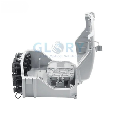


GL-FDB-H324 24-Core Outdoor Fiber Distribution Box
The GL-FDB-H324 outdoor fiber distribution box links feeder cable to subscriber drops at an FTTx termination point. A 340 × 240 × 96 mm PC+ABS housing brings together splicing, passive splitting and distribution, with 24-core capacity, two cable inlets, 24 outlets and IP65 protection. Wall and pole mounting, cassette-type SC adapter installation and a flip-up distribution panel support site-specific layouts; select the optical assembly within the listed maximum 1:24 split ratio.
|
|
Two Feeder Entries and 24 Drop OutletsProduct line: FTTx Fiber Distribution / Termination Boxes A shared point for feeder preparation, protected splices and the outgoing drop schedule. 24 cores · Maximum split ratio 1:24 · IP65 · Wall / pole mounting |

SC Adapter Panel and Feeder Access
|
|
Open the Distribution Panel to Reach the Feeder RouteThe internal view shows the SC adapter panel, routing guides and cable-fixing area within the enclosure. Separate paths organize the feeder, pigtails and drops around their assigned connection positions. Specify the adapter quantity, SC polish and splitter assembly on the component list. The photograph illustrates a loaded sample; the supplied optical parts follow the agreed order configuration. |

Configuration Features for Feeder-to-Drop Work
Assign the Two Inlets and 24 Outlets
The entry layout is specified as IN 2 OUT 24. Allocate feeder cables and outgoing drops on the node drawing before selecting seals and labels. This makes the cable path through the enclosure explicit when one feeder serves several customer connections or a second inlet is reserved for the planned route.
Size the Optical Circuit Within the 1:24 Limit
The stated maximum split ratio is 1:24, while the enclosure capacity is 24 cores. Select the splitter circuit, package and optical connections as a complete arrangement. Confirm module fit and the applicable loss measurements with the chosen assembly so the optical design follows the actual component list.
Specify the Cassette-Type SC Arrangement
SC adapters are installed in a cassette-type arrangement. Select the required adapter loading, matching pigtails and connector polish, then identify the output positions on the termination schedule. This gives assembly and field teams a common layout for assigning customer fibers and checking the installed components.
Keep Mechanical Fixing Ahead of Fiber Routing
Clamps secure feeder and drop cables while the enclosure combines splice fixation, reserve-fiber storage and distribution. Prepare the jacket transition at the appropriate fixing point, then route fibers through their separate paths. The selected cable construction and retention parts should be shown together in the installation instructions.
Use Panel Access for Feeder Preparation
The distribution panel flips up to expose the feeder work area, and an express port is described for feeder placement. Define the cable preparation, route and required through-fiber handling when specifying that entry. Leave clearance for the panel movement and the selected leads during inspection or later connection work.
Match the IP65 Housing to the Installation Kit
The fully enclosed PC+ABS body uses brackets and metal screw fastening, with an IP65 protection designation. Choose the wall or pole package to suit the site and include the corresponding cable seals and plugs. Review the closure and entry configuration as part of the acceptance requirements for the delivered assembly.
24-Core Outdoor Distribution Box Technical Data
|
Item |
Specification |
|---|---|
|
Product name |
Outdoor Distribution Box |
|
Enclosure dimensions |
340x240x96 mm |
|
Maximum fiber capacity |
24 cores |
|
Maximum split ratio |
1:24 |
|
Cable entry / exit ports |
IN 2 OUT 24 |
|
Cable diameter (listed) |
Φ16mm |
|
Mounting methods |
pole, wall-mounting |
|
Protection rating |
IP65 |
The Φ16 mm entry is the listed cable diameter. Confirm the applicable feeder inlet and its seal range; size each drop seal separately for the actual drop cable. Cable-entry counts, fiber capacity and optical split ratio describe different parts of the configuration.
|
Item |
Specification |
|---|---|
|
Product model |
GL-FDB-H324 |
|
Product line |
FTTx fiber distribution / termination boxes |
|
Housing material |
PC+ABS |
|
Enclosure construction |
Fully enclosed housing with brackets and metal screw fastening |
|
Cable management |
Feeder/drop clamping; splicing, fixation, storage and distribution |
|
Adapter arrangement |
Cassette-type SC adapter installation |
|
Panel access |
Flip-up distribution panel; express port for feeder cable placement |
|
Installation environment |
Indoor or outdoor, with the specified entry seals and mounting parts |
FTTH and FTTx Deployment Scenarios
Street-Level FTTH Drops from a Shared Feeder
A group of homes needs an organized place to separate feeder preparation from individual customer drops. Position the GL-FDB-H324 at the planned wall or pole distribution node and map the outgoing cables to its 24 drop outlets. Its 24-core capacity and listed 1:24 maximum split ratio provide the enclosure and circuit limits for that layout. Choose the passive splitter assembly and SC termination components for the network design. Before ordering, agree the inlet seals, drop-cable profiles, populated positions and output labels against the subscriber connection schedule.
Building-Entry Fiber Distribution with Internal Access
At a building entry, a crowded cable route can obstruct access when a technician adds or checks a customer connection. Use the GL-FDB-H324 as the feeder-to-drop junction, with cable clamping at the preparation points and pigtails routed to the cassette-type SC panel. The flip-up arrangement provides access to the feeder work area within the 340 × 240 × 96 mm housing. Confirm the wall fixing surface, lid clearance, splice loading and any splitter package. Specify the feeder-entry preparation and spare-fiber arrangement before approving the internal layout.
Campus Fiber Handover Between Outdoor and Indoor Routes
A campus route may bring an outdoor feeder to a building while requiring separate outgoing fibers for local network equipment. Install this distribution box at the agreed handover location and assign the incoming cable and building drops through their designated paths. Use the clamping, splicing and SC adapter arrangement to organize that transition, with the optical circuit selected for the connected equipment. Confirm cable construction and sealing, connector polish, mounting hardware and the environmental requirements at the site. The supplied configuration should follow the project drawing and connection list.
Plan the Wall or Pole Position
Select a location that supports the enclosure and its cable approach. For a wall, confirm the fixing pattern and substrate; for a pole, specify the support dimensions and matching bracket set. Allow the cover and distribution panel to open with the populated leads in place.
Route the feeder to its preparation point before arranging the drops. Check the cable jacket diameter, clamp parts and sealing components together, then record the fiber assignments and output labels on the node drawing.
Order Details for the GL-FDB-H324
|
Order item |
Information to provide |
|---|---|
|
Optical assembly |
Fiber allocation up to 24 cores; splitter circuit up to the listed 1:24 ratio; module package and supplied parts |
|
SC termination |
Adapter quantity, cassette arrangement, required SC polish and matching pigtails |
|
Feeder and drop cables |
Cable constructions and outside diameters; applicable Φ16 mm inlet; seals, plugs and retention parts |
|
Mounting and access |
Wall or pole kit, support drawing, cover / panel clearance and feeder preparation at the express entry |
|
Project acceptance |
Approved loading drawing, inspection requirements, node labels, quantity and packaging instructions |
For a quotation, send the cable schedule and proposed optical loading with the installation details. Glory Optical can review the GL-FDB-H324 enclosure assembly, component selection, project labels and packing against that specification.
Browse Fiber Optic Termination Boxes
About Glory Optical
|
Glory Optical facility, Ningbo |
Glory OpticalFounded in 2008 · Ningbo, China · OEM/ODM support Ningbo Glory Optical Communication Co., Ltd. manufactures passive fiber optic products and supplies telecom operators, ISPs, contractors, distributors and OEM/ODM buyers. Our portfolio covers fiber boxes, splice closures, PLC splitters, fiber optic cables, patch cords, pigtails, adapters, MTP/MPO assemblies and installation accessories for fiber network projects. Manufacturing & OEM/ODM SupportManufacturing capabilities across our product families include mold development, enclosure molding, component assembly and fiber cable assembly. OEM/ODM projects can cover drawings, product configuration, samples, branding, labels and packaging, according to the selected product and confirmed requirements. |

Testing Capabilities
Glory Optical supports inspection and testing according to confirmed product specifications and order requirements. The following videos show examples from our testing activities.
Water Spray Testing |
Sealing Performance Testing |
Water Resistance Testing |
Specification Review & Project Documentation
Before batch production, confirm the drawing or sample, product configuration, inspection requirements and packing details. For connectorized products, applicable inspection can include insertion loss, return loss and connector end-face checks. Datasheets, drawings and applicable test documents can be discussed for the order.
Discuss Your Product or Project Requirement
Send the product model, quantity, application and required configuration for quotation or sample discussion. Include any drawing, labeling, packaging and documentation requirements so our team can review the order details.
Email: sales@gloryoptic.com
Hot Tags: outdoor distribution box, China outdoor distribution box manufacturers, suppliers, factory, fiber closure box, fiber distribution box, fiber optic box outdoor, fiber optic splicing box, fiber splice box, terminal box fiber