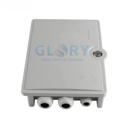


IP68 Fiber Distribution Box for Outdoor Feeder-to-Drop Nodes
This fiber distribution box brings feeder fixation, protected splicing, fiber storage and adapter-based distribution into one outdoor access node. It connects the incoming network to subscriber-side drop paths, with the internal optical components specified as a loaded project assembly. The enclosure layout, connector interface and splitter circuit should be approved together so the mechanical box and optical bill of materials describe the same supplied configuration.
 |
Open assembly showing the adapter area, routed fibers and accessible cable-entry face. |
 |
Closed front view for checking the cover and cable-entry arrangement against the drawing. |
 |
Example loaded configuration with routing, adapter area and lid labels visible. Confirm supplied components on the BOM. |
Design details
Six Configuration Details for Project Selection
1. IP68 Housing and Cable-Entry Sealing
The IP68 enclosure provides the specified ingress-protection level for the approved assembled configuration. Its cover closure, fitted entries and unused-port sealing form one protective system. Confirm the immersion conditions and test configuration for the installation site so the rating applies to the supplied box, cable profiles and sealing parts.
2. Separate Adapter and Splice Capacities
Eight adapter positions and a maximum of 12 fusion splices are separate planning limits. Keeping both values on the port map helps buyers specify external connection positions and internal joint storage without treating them as interchangeable. Adapter format and simplex or duplex arrangement determine the final optical-channel layout.
3. Optional PLC Splitter Integration
A loaded assembly can be specified with a 1×8 or 1×16 PLC splitter option. Integrating the circuit in the enclosure consolidates its routing with the splice and adapter layout. Approve the splitter package, output allocation and connectorization, particularly when the number of optical outputs differs from the adapter-position count.
4. ABS+PC Across the Stated Working Range
The ABS+PC housing is specified for operation from −40°C to +65°C. These defined material and temperature fields let procurement compare the enclosure with the actual outdoor site requirement. Installation and storage limits, flame class and impact performance remain separate requirements rather than being inferred from the operating range.
5. Four Listed Cable-Entry Openings
The cable-entry arrangement is listed as four Ø20 mm openings. This opening specification is distinct from the cable diameter accepted by an individual gland or sealing insert. Defining each cable profile and its matching seal before ordering helps prevent a cable-entry package that does not fit the supplied feeder or drop cable.
6. Defined Envelope and Mounting Options
The published enclosure envelope is 280 × 220 × 110 mm, with wall, pole and strand mounting identified. Recording that envelope with the bracket, cable exits and cover-opening clearance helps the installer assess the complete working space. Mounting hardware and accessories should be listed in the supplied project package.
Project configuration
Supply State and Configuration Options
Enclosure and optical assembly
Specify the enclosure supply contents first, then list any adapters, pigtails, splice components and PLC splitter included in the loaded assembly.
Adapter and channel map
SC/APC or LC/APC options are listed. Approve the adapter body and simplex/duplex arrangement together with the channel numbering and fiber-routing drawing.
Mounting and identification
Choose wall, pole or strand mounting and identify the required hardware. Confirm color, port labels, product identification, accessory packing and carton marks.
Technical data
General Technical Specifications
|
Parameter |
Product data |
Ordering / engineering note |
|---|---|---|
|
Product name |
IP68 Fiber Distribution Box |
Use the confirmed manufacturer part number and drawing revision on the order. |
|
Product family |
Outdoor fiber optic termination / distribution box |
For passive feeder-to-drop FTTx nodes. |
|
Ingress protection |
IP68 |
Rating applies to the approved assembled and sealed configuration; agree the required test conditions. |
|
Housing material |
ABS+PC |
Record the housing material on the approved drawing and order. |
|
Operating temperature |
−40°C to +65°C |
Working range; do not substitute an installation or storage limit. |
|
Overall dimensions |
280 × 220 × 110 mm |
Published enclosure envelope; obtain the mounting and clearance drawing. |
|
Color |
Black in the product photographs; gray and white listed as options |
Confirm finish and color on the approved sample. |
|
Mounting |
Wall / pole / strand |
State the selected mounting method and included hardware. |
|
Cable-entry specification |
4 × Ø20 mm openings |
Opening specification is not the accepted cable-OD range of the seal. |
|
Sealing arrangement |
Mechanical cover closure and sealed cable entries |
Confirm entry seals, unused-port plugs and the supplied assembly drawing. |
Capacity boundary
Model and Capacity Table
|
Published product identifier |
Adapter positions |
Splice capacity |
Overall dimensions |
Configuration note |
|---|---|---|---|---|
|
IP68 Fiber Distribution Box |
8 adapter positions |
Up to 12 fusion splices |
280 × 220 × 110 mm |
SC/APC or LC/APC configuration selected on the order; optical-channel count follows the adapter map. |
Approve the supplied port map
An adapter position, an optical channel, a fusion splice and a splitter output describe different parts of the assembly. State the exact adapter form and termination route for every active path.
Optional optical circuit
PLC Splitter Configuration
|
Ordered configuration |
Optical function |
What to approve |
|---|---|---|
|
No splitter selected |
No optical splitting circuit |
State enclosure-only, adapter-loaded or pigtail-loaded supply contents. |
|
1×8 PLC option |
One optical input / eight optical outputs |
Confirm package, input path, output termination, lead lengths and assembled port map. |
|
1×16 PLC option |
One optical input / sixteen optical outputs |
Approve the full output allocation and adapter layout; sixteen outputs do not establish sixteen external ports. |
Specify loss for the selected optical assembly
The enclosure itself is a protective mechanical product. Assign insertion loss, return loss and worst-output splitter loss to the selected optical components and measurement boundary. Agree the required wavelengths, acceptance limits and report format for the loaded assembly.
Cable and interface fit
Cable and Connector Compatibility
|
Item |
Configuration scope |
Confirm before ordering |
|---|---|---|
|
Feeder cable |
Entry and internal fixation selected for the project |
Measured OD, profile, fiber construction, strength member and matching seal. |
|
Drop cable |
Matched to the selected exit or termination arrangement |
Flat or round profile, dimensions, exit method, retention and spare-entry sealing. |
|
Adapter and connector |
SC/APC or LC/APC options listed |
Adapter body, simplex/duplex form, connector polish, keying and exact mating parts. |
|
Hardened outdoor interface |
A separately specified connector and sealing assembly |
Do not infer an outdoor interface family or cross-brand fit from SC/APC polish alone. |
|
Pigtail and splitter leads |
Defined by the loaded optical BOM |
Fiber type, buffer profile, length, routing and splice/connector destination. |
|
Cable-entry fit |
4 × Ø20 mm published openings |
Confirm the actual gland or insert cable range; no accepted cable-OD range is published. |
|
Optical acceptance |
Project-specific for the installed components |
Agree applicable insertion loss, return loss, splitter loss, wavelengths and test records. |
Network placement
IP68 Fiber Distribution Box Applications and Solutions
IP68 Fiber Distribution Box for Pole-Mounted FTTH Nodes
An outdoor access node assembled from an unspecified box and loose optical parts can leave cable fixation, splice storage and subscriber patching unresolved. This IP68 fiber distribution box combines those functions within one ABS+PC enclosure and provides a defined eight-position adapter layout. Mount it at the feeder-to-drop transition on a roadside or neighborhood pole, using the approved bracket and cable-support package. SC/APC or LC/APC interfaces connect the selected pigtails and drop assemblies. Before ordering, confirm pole dimensions, feeder construction, sealing inserts, port map, splitter requirement, unused-port protection and the optical acceptance records for the loaded configuration.
Building-Exterior and MDU Distribution
A wall-mounted box chosen only by its nominal capacity may fit the splice count while leaving insufficient space for cable exits or future access. The 280 × 220 × 110 mm enclosure brings splicing, routing and adapter distribution together at a building-entry or MDU access node. Its stated operating range is −40°C to +65°C, and the mounting arrangement can be matched to the wall and feeder route. Specify the incoming cable, subscriber drop profiles and selected connector polish. Procurement should also confirm cover-opening clearance, site exposure, optical components, labels and any building-specific material or fire requirements.
IP68 Fiber Distribution Box for Handhole Projects
A flooded access chamber exposes more than the lid: cable entries, unused openings and the assembled connection system must also match the site conditions. For a handhole project, use this IP68 fiber distribution box only with the selected cable-entry configuration and immersion evidence approved for that location. Position it at the feeder-to-drop distribution node with accessible splice storage and protected adapter connections. Provide feeder and drop-cable dimensions, interface details and chamber layout. Before purchase, confirm mounting, drainage assumptions, service-loop space, cover access, immersion depth and duration, and the documentation identifying the tested assembly.
Selection and installation
Five Checks Before Sample and Batch Approval
1. Define the network function.
Specify termination, splicing and distribution, then identify whether a PLC circuit is required.
2. Approve the capacity map.
List adapter positions, actual optical channels, splice quantity and splitter outputs separately.
3. Match every cable entry.
Provide the cable profile and measured OD for each inlet or exit, including unused-entry sealing.
4. Confirm the mounted envelope.
Check the enclosure, bracket, lid-opening path, cable exits and maintenance clearance against the site drawing.
5. Approve the loaded sample and evidence.
Review routing, interfaces, labels and supplied accessories; agree the sealing configuration and optical acceptance records before batch release.
Ordering configuration
Prepare a Quote-Ready Product Configuration
RFQ line to copy and complete
Please quote IP68 Fiber Distribution Box, ABS+PC, operating range −40°C to +65°C, quantity [ ], drawing / part number [ ], adapter layout [ ], splice plan [ ], supply contents [ ], PLC [none / 1×8 / 1×16 with output map], cable profiles and OD [ ], matching seals [ ], mounting hardware [ ], required ingress test conditions [ ], optical records [ ], labels [ ] and packaging [ ].
OEM and project configuration
Configure the Box Around the Approved Project BOM
Drawing and BOM Review
Identify the housing reference, adapter layout, cable entries, splice route and any PLC circuit on one controlled drawing. Keep the approved revision with the order.
Sample and Assembly Approval
Review mounting fit, cover access, cable-entry seals, routing, connector mating and labels on the selected loaded or unloaded sample before releasing the batch.
Labels, Packing and Evidence
Specify product identification, port numbering, accessory bags, carton marking and the document pack. Agree the applicable optical and enclosure evidence for the exact supplied configuration.
Company background
Why Glory Optical for Fiber Distribution Box Projects
Glory Optical Communication was founded in 2008 and is based in Ningbo, Zhejiang, China. The company operates a 20,000 m² manufacturing facility, with a product portfolio covering fiber boxes, splice closures, PLC splitters and fiber assemblies. For this distribution box, the relevant capabilities are enclosure tooling, tray and adapter assembly, splitter integration, drawing review and project packaging.Enclosure and Assembly Coordination
Mold development, enclosure assembly and material preparation support the housing, cable-entry parts and internal routing layout. Confirm the supplied configuration against the approved product drawing and sample.
Project Documentation and Optical Checks
Loaded-box projects can be reviewed with adapters, pigtails, splitter routing, labels and packing as one BOM. Optical checks for connectorized components can include insertion loss, return loss and end-face condition, with the applicable limits agreed for the order.
|
|
Project configuration
Confirm the Port Map, Cable Seals and Loaded Assembly
Send the IP68 fiber distribution box reference, adapter and splice layout, cable profiles, optional PLC circuit, mounting method, quantity and required documentation. Glory Optical can review the project configuration before quotation and sample approval.
Hot Tags: ip68 fiber distribution box, China ip68 fiber distribution box manufacturers, suppliers, factory, Outdoor Fiber Optic Junction Box, Nid Box, fiber optic box outdoor, Optical Fiber Distribution Box, fiber outlet box, box fiber