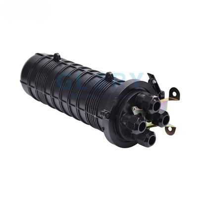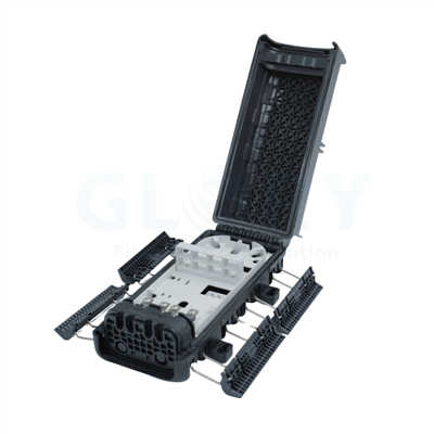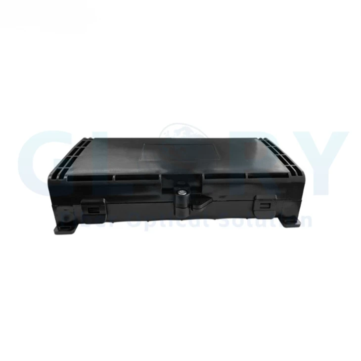
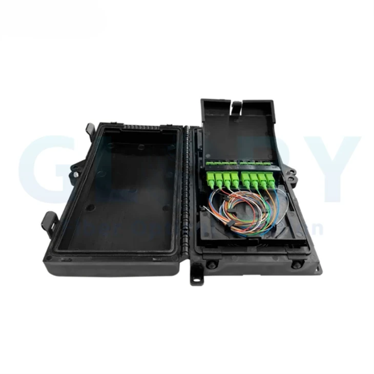


8-Core FTTx Termination Box Overview
Network Function
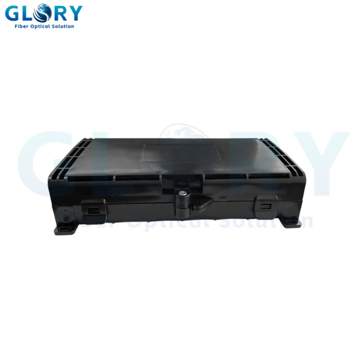
This enclosure provides a protected point for bringing feeder or distribution fiber into an FTTx access node, organizing the internal fiber path, and presenting a termination arrangement for the next cable segment. Its 8-core capacity fits compact subscriber, floor, building-edge and small outdoor distribution locations where a larger 16- or 24-core box would add unused space.
Product Configuration
The base enclosure configuration covers 8-core fiber management, a black ABS housing, IP65 protection, −25°C to +60°C operation and wall or pole mounting. Adapter quantity, splice arrangement, cable-entry layout, accepted cable diameter, splitter loading and connector interface are selected through the project BOM and approved drawing
FTTx Fiber Optic Termination Box Selling Points
8-Core Fiber Organization
The enclosure is listed for up to eight fibers and incorporates defined internal routing paths. Compared with using an oversized high-capacity box at a small access node, the compact capacity keeps the project BOM aligned with the actual subscriber or branch count while reserving protected space for termination and stored fiber.
IP65 Environmental Protection
IP65 protection addresses dust ingress and water-jet exposure for indoor or outdoor FTTx distribution points. This provides a clearer installation boundary than an unrated indoor box. IP65 does not cover continuous underwater use, so handhole or flood-prone projects require an enclosure and sealing specification selected for those conditions.
Black ABS Housing
The black ABS enclosure operates from −25°C to +60°C. These values let procurement teams compare the box with the project environment before ordering, instead of assuming the material, color and temperature limits of another termination-box family also apply to this model.
Wall or Pole Installation
Two mounting methods are listed: wall mounting for building edges, corridors or telecom areas, and pole mounting for access-side routes. The alternative installation positions reduce the need to source separate enclosure families, while the final RFQ should still identify the selected mounting method and the required bracket or fastener set.
Hinged Service Access
A hinged cover and latch mechanism provide access to the splicing and fiber-management areas. Installers can reopen the enclosure without removing the mounted base, which supports route inspection and service work. The latch and seal should be closed evenly after intervention to preserve the IP65 enclosure protection.
Project-Selected Adapter Interface
SC, LC and FC adapter types can be configured instead of using one fixed interface. This separates enclosure selection from interface selection and lets the buyer match existing patch cords or pigtails. The RFQ should state adapter quantity, connector polish, simplex or duplex format, and whether adapters and pigtails are factory fitted.
Product Views


FTTx Fiber Optic Termination Box Technical Specifications
The tables below organize the enclosure specifications and the project-defined configuration items required for ordering.
General Technical Specifications
| Parameter | Specification | Technical Meaning |
|---|---|---|
| Product name | FTTx Fiber Optic Termination Box | Compact termination and fiber-management enclosure for FTTx access points |
| Product category | Fiber optic termination / distribution box | Protects and organizes fiber between network cable segments |
| Application | FTTx | Applicable to FTTH and FTTB access-node layouts when the ordered interface matches the network design |
| Fiber capacity | Up to 8 cores | Fiber capacity is not the same as adapter-port count or splice capacity |
| Ingress protection | IP65 | Dust-tight and protected against water jets within the IP65 test boundary; not intended for continuous submersion |
| Enclosure material | ABS | Black ABS enclosure housing |
| Color | Black | Standard enclosure color |
| Operating temperature | −25°C to +60°C | Specified enclosure operating range |
| Mounting method | Wall-mounted or pole-mounted | Mounting hardware should be matched to the selected installation method |
Model and Capacity Table
| Model Name | Fiber Capacity | Material / Color | IP Rating | Temperature | Mounting |
|---|---|---|---|---|---|
| FTTx Fiber Optic Termination Box | Up to 8 cores | ABS / Black | IP65 | −25°C to +60°C | Wall or pole |
Optical-component configuration: insertion loss, return loss, splitter loss, operating wavelength, uniformity, PDL and directivity depend on the adapters, pigtails or PLC splitter installed in the enclosure. Define these components and their test limits as separate items in the project BOM.
Ordering Configuration for OEM and Project Procurement
Use the enclosure parameters as the product baseline, then define the interface and cable-management details before drawing approval or batch production.
| Ordering Item | Configuration Status | Information to Put in the RFQ or BOM |
|---|---|---|
| Fiber capacity | Up to 8 cores | Working fibers, spare fibers and required storage arrangement |
| Adapter interface | SC, LC or FC configurable | Connector family, APC or UPC polish, simplex or duplex format, and adapter quantity |
| Splice arrangement | Project-defined splice count and internal routing layout | Required splice count, sleeve holder, tray arrangement and pigtail quantity |
| Cable compatibility | Project-defined cable entries and diameter range | Feeder and outgoing cable construction, outside diameter, strength member and entry direction |
| PLC splitter | Optional project configuration | Split ratio, package type, connectorization, fiber length and optical test limits if a splitter is required |
| Mounting accessories | Wall or pole installation is listed | Selected mounting method, bracket requirement, pole diameter range and fastener responsibility |
| Enclosure marking | OEM/ODM project support is available | Logo artwork, port numbering, warning labels, carton marks and language |
| Documentation | Project BOM and drawing confirmation are supported | Approved drawing revision, component list, inspection items and packaging specification |
FTTx Fiber Optic Termination Box Applications and Solutions
FTTx Fiber Optic Termination Box for FTTH Last-Mile Distribution
Using a large distribution enclosure at a small subscriber branch can consume wall or pole space and leave most capacity unused. This 8-core FTTx fiber optic termination box provides a compact protected point for organizing feeder-to-drop fiber before the final customer connection. It can be positioned at a building edge, residential distribution point or small neighborhood branch. The ordered interface must match the pigtails, adapters and downstream FTTH cable. Before procurement, confirm the actual subscriber count, splice requirement, connector polish, cable outside diameter and whether a splitter is supplied separately.
Pole-Mounted Outdoor FTTx Access
An indoor box or an enclosure without an ingress rating can expose fiber routing and terminations to dust and rain at an aerial access node. The black ABS housing, IP65 protection and pole-mount option define a clearer boundary for outdoor FTTx distribution. Install it on the pole between the feeder or distribution cable and the outgoing access cable route. Cable clamps, adapters and pigtails must match the selected cable construction. The RFQ should identify pole dimensions, bracket supply, cable-entry direction, cable diameter and the required grounding treatment for any armored cable.
FTTB and MDU Floor Distribution
Routing building fibers through an improvised junction point makes bend control, splice protection and later service identification difficult. The enclosure's 8-core capacity, hinged access and internal routing arrangement create a defined floor or riser distribution point for FTTB and small MDU networks. It can be wall-mounted in a corridor, utility area or telecommunications space between the building feeder and floor-level links. Select SC, LC or FC only after checking the existing patching system. Include the required flame rating and local building-code conditions in the project specification.
GPON or XGS-PON Access Node
Treating every FTTx enclosure as a splitter terminal can create an incorrect loss budget and a BOM that does not fit the internal space. This box provides passive fiber termination and organization at a compact GPON or XGS-PON access node. Position it where feeder, distribution or drop fibers require protected transition and service access, and match the adapters and pigtails to the network connector standard. If PLC splitting is required, confirm the ratio, package dimensions, fiber lengths, worst-port loss requirement and routing layout before production.
Selection and Installation Guidance
Choose This 8-Core Enclosure When
- The node requires no more than eight managed fibers.
- IP65 matches the expected dust and water-jet exposure.
- The installation is wall-mounted or pole-mounted.
- The project can define adapters, splices and cable entries in the approved configuration.
Move to Another Product Family When
- The network requires more than eight fibers or a verified high splice capacity.
- The site is subject to flooding or continuous submersion.
- A factory-loaded PLC splitter or hardened connector port is mandatory.
- The project requires a specific IK rating, flame rating, cable-retention value or cable-entry range.
Installation Sequence
Check enclosure capacity, adapters, pigtails, splice parts, cable entries and the selected wall or pole hardware against the BOM and drawing.
Confirm service clearance, cable approach, drainage path and a mounting surface or pole arrangement that supports the selected hardware.
Use the cable-entry parts specified for the actual outside diameter and cable profile; secure the strength member or armor according to the approved design.
Organize fibers through the defined paths, protect fusion splices and avoid routing below the bend limit specified for the installed fiber and cable.
Verify identification and optical continuity, inspect the sealing surfaces, then close the hinged cover and latch evenly before recording the installed configuration.
Why Glory Optical for FTTx Termination Box Projects
Passive ODN Manufacturing in Ningbo
Glory Optical Communication was founded in 2008 and operates a 20,000 m² manufacturing facility in Ningbo, Zhejiang. R&D, molding, assembly and testing are handled under one roof. Its product scope includes fiber termination and distribution boxes, splice closures, PLC splitters, adapters, patch cords, pigtails and pre-terminated assemblies.
Project Configuration and Repeat Supply
For an 8-core FTTx termination-box order, support can cover enclosure configuration, cable-entry planning, adapter and pigtail selection, drawing and BOM confirmation, labeling, packaging and batch production. The company also lists optical, environmental and mechanical test equipment as part of its OEM/ODM capability; the required inspection items and acceptance values should be written into the project specification.
From sample verification to project configuration
Confirm the physical interface and cable code before bulk production, then lock the approved configuration into drawings and order codes.
3-Year Service Policy
Defined return, replacement and repair support is available according to the applicable warranty terms and confirmed order documentation.
OEM/ODM Configuration
Port count, cable length, splitter structure, mounting accessories, labeling and packaging can be configured for the project.
Sample & Drawing Approval
Sample evaluation and approved drawings help confirm interface fit, sealing and cable compatibility before volume deployment

Our Quality Promise
Comprehensive 3-Year Warranty
We confidently back all our products with a 3-year warranty. Our specific service policy is: within one year for quality issues, we take full responsibility for returns; within two years, for replacements; and within three years, for repairs.
Clear & Competitive MOQ
We welcome both trial and bulk orders. Our standard Minimum Order Quantity (MOQ) is 50 units. We also offer free samples for testing to help you evaluate our quality with confidence.
Fast & Reliable Logistics
We guarantee delivery within 10 days for standard items. Our logistics advantage includes cost-effective door-to-door service to simplify shipping for you.
Our Foundation
Backed by 18 years of experience since 2008, we control quality from our own factory, accept OEM/ODM requests, and maintain ready stock for wholesale. We focus on delivering the optimal balance of price and quality directly to end customers worldwide.
Your trust is our priority. Partner with us for dependable fiber optic solutions supported by clear promises.
Hot Tags: fttx fiber optic termination box, China fttx fiber optic termination box manufacturers, suppliers, factory, fiber optic box outdoor, fiber to the box, outdoor fiber distribution box, outdoor fiber junction box, outdoor fiber optic distribution box, outdoor fiber splice box