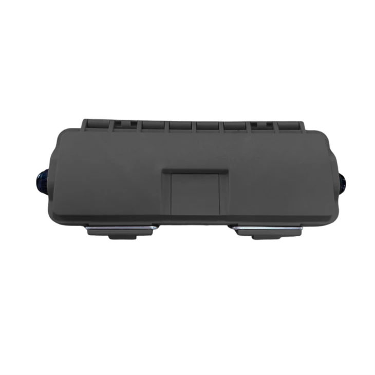
Product overview
An outdoor fiber terminal box for cable extension
When a single cable cannot cover the distance between two splice closures, the GL62DW-41-P creates a protected intermediate connection point. It addresses route changes and projects using standardized cable lengths without requiring a larger distribution enclosure solely to house a small splice connection.
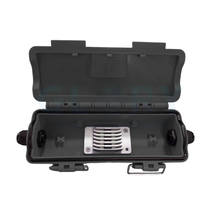
The PG7 version combines mechanical cable sealing with a hinged enclosure and a page-turning internal structure. The maximum 12F rating refers to fiber splicing capacity; it is not a count of subscriber connector ports.

Six technical features
Built around the cable connection point
01 / SPLICE CAPACITY
Up to 12 fiber splices
A maximum 12F splicing capacity supports small cable extension joints between separated closures. The page-turning structure gives access to the internal fiber management area, helping technicians organize the joint around the required splice count. This capacity describes splices and should be checked against the project fiber schedule.
02 / CABLE SEALING
PG7 entries for Ø3–6.5 mm cables
The PG7 version accommodates cables with an outer diameter of 3–6.5 mm and uses mechanical sealing. A defined diameter range gives buyers a concrete cable-fit check before ordering, reducing the risk of pairing an unsuitable cable with the entry seal. Confirm the jacket profile and cable construction as well as the measured diameter.
03 / INGRESS PROTECTION
IP68 enclosure rating
The datasheet specifies IP68 for the enclosure and references a sealing check at 15 kPa internal pressure in water for 15 minutes, with no bubbles as the stated requirement. These defined conditions support a project sealing review. Request applicable test documentation and confirm site exposure when specifying the box.
04 / MECHANICAL PROTECTION
IK09 impact rating
An IK09 rating is stated for the enclosure. The accompanying impact test specifies a 1 kg steel ball dropped from 1 m at four axial positions, with no internal damage or effect on sealing as the requirement. This gives procurement teams a defined mechanical reference when assessing exposed outdoor mounting locations.
05 / OPERATING ENVIRONMENT
−40°C to +65°C operation
The specified working temperature extends from −40°C to +65°C, allowing the enclosure to be evaluated against the expected outdoor operating conditions. Use this range in the site specification and account for local enclosure temperatures. Installation and storage temperature limits should be confirmed separately during project review.
06 / MOUNTING & IDENTIFICATION
Compact wall or pole deployment
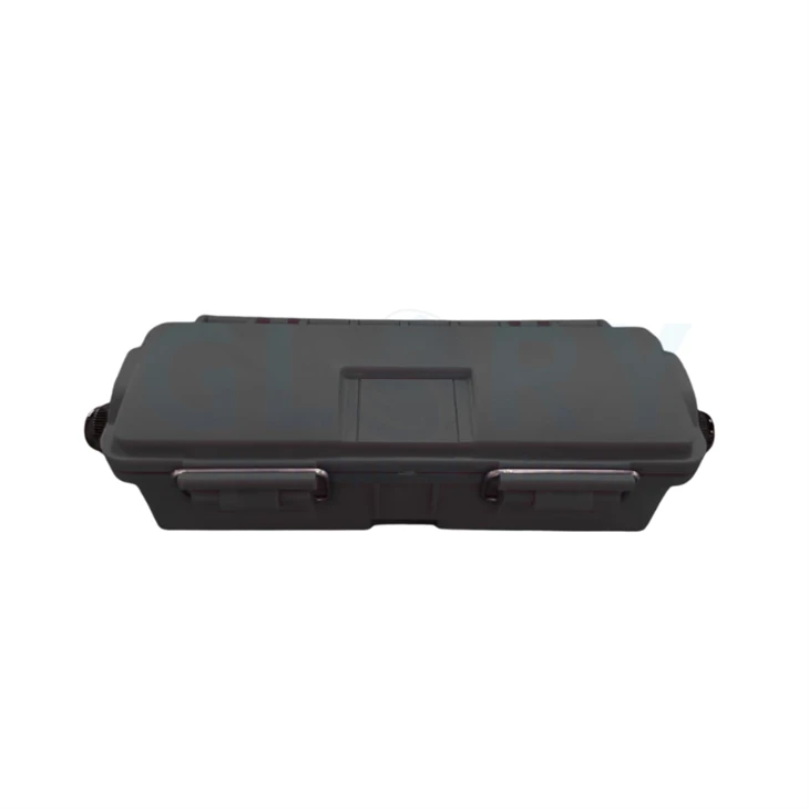
The black housing measures 44 × 196 × 75 mm (H × W × D), with a stated tolerance of ±2 mm, and supports wall or pole mounting. Its defined footprint helps assess available mounting space. Laser logo labeling is listed in the specification, allowing the marking requirement to be included in the order review.
Product family & configuration
Specify the version and mounting accessory
The product coding diagram uses separate positions for product type and installation accessory. Check both fields when requesting the complete order code.
Product type field
P = PG7 version. This page presents the PG7 cable splice model GL62DW-41-P.
M = MPO version. MPO is listed as an alternative type code. Request its own interface, fiber configuration and performance specification before selection.
Installation accessory field
P = Pole mounting. Specify the pole dimensions and required mounting hardware.
W = Wall mounting. Specify the mounting surface and fixing arrangement. The accessory code is separate from the PG7 product type code.
Technical data
Outdoor fiber terminal box specifications
Specifications below are taken from the supplied product datasheet. Dimensions retain the source order of height × width × depth.
| Parameter | GL62DW-41-P / PG7 version |
|---|---|
| Product family | Fiber terminal box / fiber termination box |
| Product function | Cable extension and connection between separated fiber splice closures |
| Maximum splicing capacity | 12 fibers |
| Dimensions (H × W × D) | 44 × 196 × 75 mm (±2 mm) |
| Housing color | Black |
| Housing material description | High-strength, environmentally friendly material; non-corrosive to metal parts, as described in the datasheet. The material grade is not specified. |
| Compatible cable diameter | Ø3–6.5 mm |
| Ingress protection | IP68 |
| Impact protection | IK09 |
| Environmental requirement | RoHS 2.0, as stated in the datasheet |
| Sealing method | Mechanical sealing |
| Internal structure | Page-turning / flip structure |
| Logo marking | Laser labeling |
| Working / operating temperature | −40°C to +65°C |
| Mounting methods | Wall mounting; pole mounting |
| Applicable environment | Outdoor application |
On narrow screens, swipe horizontally to read the full table.
Model and Capacity Table
| Product model | Version | Max. splicing | Cable diameter | Dimensions H × W × D | Mounting |
|---|---|---|---|---|---|
| GL62DW-41-P | PG7 | 12F | Ø3–6.5 mm | 44 × 196 × 75 mm (±2 mm) | Wall / pole |

Performance Test References
| Item | Stated test conditions | Stated requirement | Reference |
|---|---|---|---|
| Sealing | Inflate to 15 kPa; place in water for 15 minutes and observe for bubbles. | No bubbles emerge from the box after the test. | IEC 61300-2-38 |
| Impact | 1 kg steel ball; 1 m drop height; 0°, 90°, 180° and 270° in the axial direction of the box. | No internal structural damage; no effect on sealing performance (IP68). | IEC 61300-2-12 |
| Vibration | 5–500 Hz; frequency change 1 octave/minute; 10 cycles, with 5–500–5 Hz as one cycle; fixed amplitude 1.5 mm below 9 Hz; test temperature +23°C ±3°C. | No internal structural damage; no effect on sealing performance (IP68). | IEC 61300-2-1 |
Cable & interface selection
Match the entry to the project cable
PG7 identifies the cable entry version. It does not specify SC/APC, a hardened connector interface or a pre-terminated assembly.
| Selection item | Documented information | Procurement check |
|---|---|---|
| Cable entry type | PG7 version | Match the selected cable to the gland and mechanical seal. |
| Cable outside diameter | Ø3–6.5 mm | Provide the measured diameter and cable drawing. |
| Cable construction / profile | The datasheet defines the diameter range. | Confirm jacket profile, strength members and internal fiber construction; diameter alone does not confirm every cable type. |
| Splice requirement | Maximum 12 fiber splices | Confirm working fiber count, splice protection and routing requirements. |
| Connectorized alternative | M = MPO version in the coding diagram | Request model-specific connector, fiber count, polish, polarity and optical data when choosing MPO. |
Applications & solutions
Outdoor fiber terminal box applications in FTTH and FTTx
Use a defined cable splice point where the route or available cable length requires an intermediate connection.
01 / ACCESS NETWORK
Outdoor fiber terminal box for FTTH cable extension
A route change can leave a planned cable too short to reach the next splice closure, while replacing the entire run adds work to the project. The GL62DW-41-P provides a mechanically sealed intermediate splice point with up to 12F capacity for extending that segment. Install it on a wall or pole between the two closure locations, using cables within the stated 3–6.5 mm diameter range. Before procurement, confirm the required splice count, cable construction, available slack, mounting accessories and the additional joint's allowance in the optical link budget.
02 / OUTDOOR PLANT
Pole-mounted connections on rural FTTx routes
Using a general indoor splice box at an exposed connection point leaves the sealing and impact requirements unresolved. The GL62DW-41-P specifies IP68, IK09 and an operating range of −40°C to +65°C, giving the project a defined outdoor enclosure specification. Position it on a pole at a planned cable extension point between adjacent closures, with compatible 3–6.5 mm cables. Confirm the pole mounting accessory code, pole dimensions, independent cable support, exposure conditions and required test documentation before ordering. Cable suspension loads must be reviewed separately from the enclosure's impact rating.
03 / BUILDING & CAMPUS
Wall-mounted joints for standardized cable lengths
Standardizing cable lengths can simplify project inventory, but a supplied segment may end before the next enclosure or building entry point. The compact GL62DW-41-P creates a defined cable connection point, with a 44 × 196 × 75 mm housing and a page-turning internal structure for splice routing. Mount it on an exterior wall along an FTTH, campus or enterprise access route, connecting cables within the PG7 diameter range. Confirm the wall fixing arrangement, splice count, cable profile, routing clearance and laser marking before releasing the project bill of materials.
Installation & selection guidance
Check the joint before selecting the accessory
Site and cable checklist
- Confirm the connection task. Identify the two cable segments, required fiber count and planned splice location. Keep the splicing requirement within 12F.
- Check cable fit. Verify the outside diameter is 3–6.5 mm and submit the cable profile and construction for gland compatibility review.
- Select wall or pole mounting. Confirm the accessory field, supporting hardware and the fixing surface or pole dimensions.
- Plan routing and support. Allow space for cable entry, fiber slack and enclosure access. Use the approved cable bend radius and independent cable support requirements.
- Confirm acceptance requirements. Agree the sealing checks, site exposure conditions and optical link acceptance criteria with the project team.


OEM & project configuration
Prepare a complete GL62DW-41-P inquiry
For an OEM outdoor fiber terminal box inquiry, begin with the documented PG7 configuration. Include project details for review of labeling, packaging and any requested changes.
| Order item | Documented baseline | Information to provide |
|---|---|---|
| Model and type code | GL62DW-41-P; P = PG7 | PG7 splice requirement; request a separate specification if selecting the M / MPO version. |
| Installation accessory | P = pole; W = wall | Mounting location, dimensions and required accessory list; confirm the complete order suffix. |
| Fiber splice count | Up to 12F | Required working fibers and splice layout. |
| Cable fit | Ø3–6.5 mm | Cable diameter, jacket profile, construction and drawing. |
| Housing and marking | Black; laser logo labeling | Logo artwork, marking position and label requirements for review. |
| Project documentation | Datasheet specifications and test references | Required drawing, applicable test report and compliance documentation. |
| Sample / packaging review | Company-level OEM / ODM support | Sample approval needs, packaging and product identification requirements. |
| Commercial inquiry | Project quotation | Quantity, destination and requested delivery schedule. |
Why Glory Optical
Manufacturing support for outdoor fiber connections
Glory Optical Communication is based in Ningbo, Zhejiang, China. Its official company profile states that the business was founded in 2008 and manufactures passive fiber optic products, including termination boxes, splice closures and FTTH cables.
For GL62DW-41-P projects, buyers can request review of cable entry fit, splice requirements, mounting accessories and laser marking, supported by the company's documented OEM / ODM workflow.
Housing tooling & assembly
The company describes mold development and enclosure assembly capability, relevant to reviewing housing geometry and the agreed product drawing.
Drawings, samples & batch supply
Its project workflow covers specification review, sample preparation and batch production, with labeling and packaging requirements confirmed for the order.
Product-specific documentation
Datasheets, drawings and applicable test or compliance documents may be requested. Agree the documentation scope for the chosen model and project.
Company information: Official company profile · OEM / ODM services
Project quotation
Specify your outdoor fiber terminal box connection
Send the GL62DW-41-P model, required splice count, cable diameter and construction, wall or pole mounting, quantity and marking requirements. Glory Optical can review the configuration for your project quotation.
Hot Tags: 12f outdoor fiber terminal box, China 12f outdoor fiber terminal box manufacturers, suppliers, factory, 24 Port Fiber Termination Box, Fiber Access Terminal Box, fiber closure box, fiber distribution box outdoor, Nid Box, Outdoor Fiber Optic Junction Box