Configuration at a Glance
Three Numbers, Three Different Design Limits
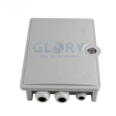
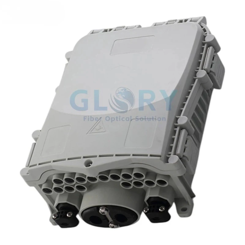
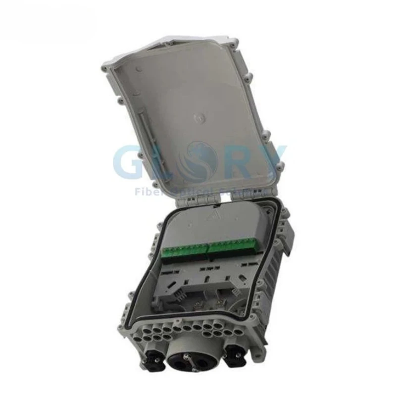
The enclosure's fiber count, connector positions and splitter space describe separate functions. Reading them separately prevents an incorrect loaded BOM.
Configuration note: adapters, pigtails, splice sleeves and PLC components are configured to order. Include the required port map and internal BOM when requesting a loaded enclosure.
Product Design Highlights
Inside the GL-ODB-16S Fiber Termination Enclosure
Six enclosure details connect the product dimensions, interfaces and protection ratings with installation and purchasing decisions.
Network Role
How the 16-Port Fiber Termination Enclosure Fits an FTTH Link
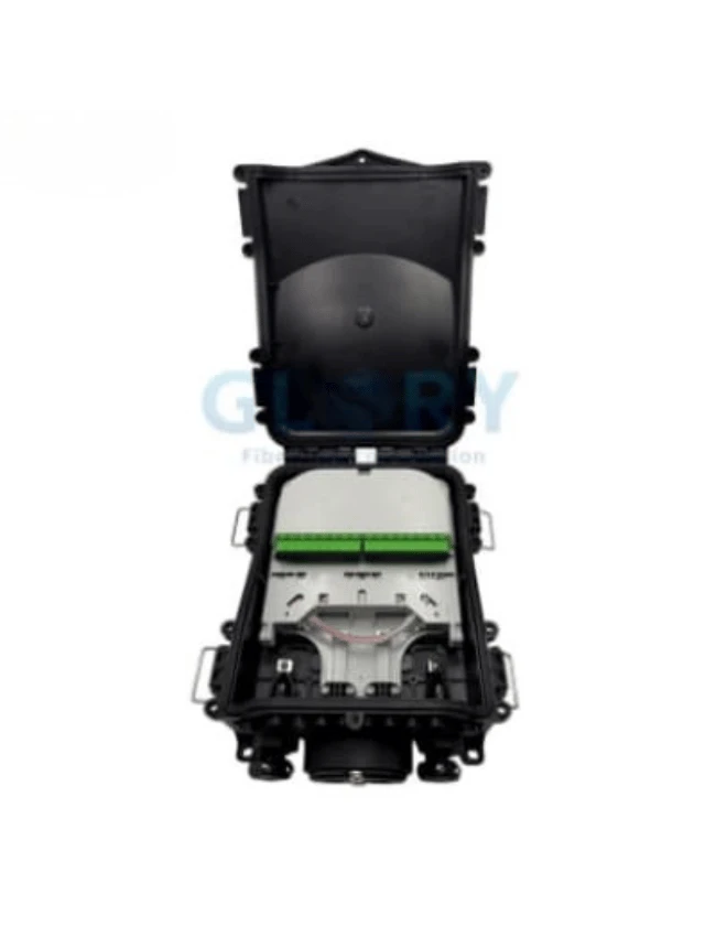
The GL-ODB-16S is positioned between the feeder route and subscriber-side distribution. The actual splice and splitter arrangement depends on the approved project BOM.
Backbone Cable
Loose-tube, skeleton or another approved cable reaches the node; the uncut entry accepts Ø8–17.5 mm.
Splice & Store
Selected fibers are routed within the 24-fiber enclosure while maintaining the stated 30 mm bend radius.
Split up to 1×16
One 1×16 PLC splitter can be accommodated when the order specifies a splitter-loaded configuration.
Up to 16 SC Drops
SC/APC or SC/UPC adapter positions connect the confirmed subscriber-side pigtail or drop arrangement.
Optical-budget note: a 1×16 split ratio describes the network topology, not the actual worst-port loss. Define connector insertion loss, return loss, splitter loss and report requirements in the project acceptance specification.
Technical Data
GL-ODB-16S Specifications and Configuration Tables
Review the enclosure capacity, environmental ratings, cable entries, connector choices and optional PLC loading before defining the project BOM.
Model and Capacity
| Model | Product Family | Fiber Capacity | Adapter Capacity | PLC Capacity | Dimensions |
|---|---|---|---|---|---|
| GL-ODB-16S | FTTH fiber termination / distribution enclosure | 24 fibers | Up to 16 SC | Up to one optional 1×16 PLC splitter | 314 × 202 × 103 mm |
Enclosure and Environmental Specifications
| Parameter | Specification | Application Note |
|---|---|---|
| Housing material | PP+GF | Polypropylene with glass fiber |
| Ingress protection | IP65 | For outdoor ingress protection; not for continuous immersion |
| Impact rating | IK10 | Enclosure impact classification |
| Temperature range | −40°C to +65°C | Specify separate installation or storage limits if required by the project |
| Cover structure | Flip-top; mechanical buckles; silicone gasket | Mechanical access for installation and service |
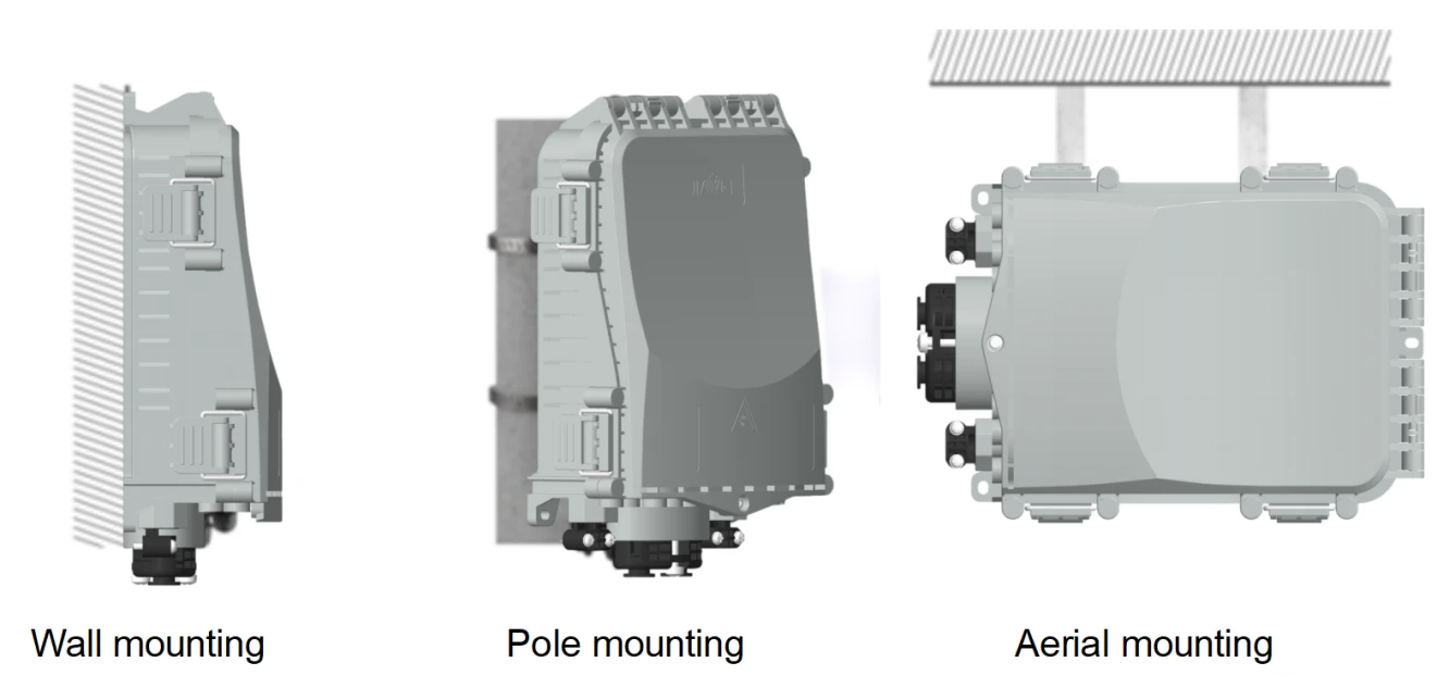
| Mounting | Wall, pole or aerial | Select the required mounting kit |
Cable and Connector Compatibility
| Interface Area | Compatibility | Quantity / Range | Ordering Requirement |
|---|---|---|---|
| Main cable entry | Loose-tube, skeleton and other compatible cable types | 1 uncut port; Ø8–17.5 mm | Cable profile and strength-member arrangement |
| Branch entries | Branch cable routing | 2 ports | Branch profile, diameter and retention |
| Adapter field | SC/APC or SC/UPC | Up to 16 | Polish, color, quantity and port map |
| Fiber routing | Connector zones and spare-fiber storage | 30 mm minimum bend radius | Pigtail length and service-loop plan |
Splitter and Optical Configuration
| Item | Enclosure Configuration | Ordering Requirement |
|---|---|---|
| PLC splitter | Up to one optional 1×16 PLC splitter | Package, fiber type, pigtail length and loaded BOM |
| Connector interface | SC/APC or SC/UPC | Adapter quantity, polish type, port map and optical acceptance limits |
| Optical acceptance | Project-defined for loaded components | Insertion loss, return loss, splitter loss, uniformity, PDL, directivity and operating wavelength as required |
Deployment Fit
Fiber Termination Enclosure for FTTH and Outdoor Access Nodes
Each scenario starts with the network problem, identifies the relevant enclosure feature and closes with the information needed before purchase.
FTTH Last-Mile Distribution
Separate splice, storage and adapter boxes can make a small subscriber node harder to document and service. The GL-ODB-16S brings 24-fiber management and up to 16 SC positions into one protected enclosure at the feeder-to-drop transition on a wall or pole. It accepts SC/APC or SC/UPC connections and an 8–17.5 mm uncut feeder. Before procurement, confirm active subscribers, splice quantity, adapter loading, polish type, branch cable sizes and whether the box is supplied empty or with a 1×16 PLC splitter.
GPON or XGS-PON Splitter Node
A patch-only terminal can require an additional housing when the PON topology calls for local splitting. This enclosure reserves space for one 1×16 PLC splitter beside a maximum 16-position SC field, allowing the loaded assembly to sit between the feeder and subscriber drops. SC/APC is common in PON links, but SC/UPC is also listed and must not be mixed within a mated path. Confirm the split ratio, splitter package, pigtail map, project optical budget and acceptance-test limits before sample approval.
Pole and Aerial OSP Distribution
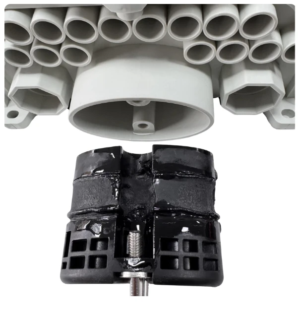
An indoor box or improvised cable seal gives an outdoor access node no defined ingress or impact classification. The GL-ODB-16S uses a PP+GF housing with IP65 and IK10 ratings and supports pole or aerial mounting across the −40°C to +65°C range. The gel-sealed main port accommodates an 8–17.5 mm cable while two branch entries organize outgoing routes. Confirm the bracket set, cable support, branch diameters, installation orientation and local wind, ice and safety requirements before release.
Rural Feeder Mid-Span Branching
Cutting a feeder at every rural distribution point creates joints even where only selected fibers need to leave the route. The uncut gel port lets an approved feeder continue through the enclosure while selected fibers are routed, stored or split for subscriber branches. Install the box on a specified wall, pole or aerial support and match the main cable to the 8–17.5 mm range. Procurement should provide the route diagram, cable construction, selected fiber count, branch profiles, port demand and loaded internal configuration.
Below-grade selection: for handholes or below-grade nodes, include drainage, flood exposure, mounting and cable-sealing conditions in the project review. IP65 does not establish continuous-immersion protection.
Technical FAQ
Questions Before Selecting This Fiber Termination Enclosure
Q: Is the GL-ODB-16S a 16-fiber or 24-fiber enclosure?
A: It has a published total capacity of 24 fibers and a separate maximum of 16 SC adapter positions. Fiber capacity and connector-port capacity describe different internal functions.
Q: Does every enclosure include 16 adapters and a 1×16 PLC splitter?
A: The page states "up to 16" SC adapters and a maximum 1×16 PLC splitter. It does not establish one universal loaded BOM. Confirm installed quantities and components in the quotation or drawing.
Q: Which connector interface can be ordered?
A: The published interfaces are SC/APC and SC/UPC. Specify one polish type for the connection path and confirm adapter, pigtail and splitter pigtail configuration together.
Q: Can the enclosure be installed in a flooded handhole?
A: IP65 does not establish continuous immersion protection. The technical installation list specifies wall, pole and aerial mounting. Send the handhole drainage and flood conditions to Glory Optical for written product and sealing confirmation.
Q: What should be done if the gel seal shows oil seepage or damage?
A: The source-page FAQ links seepage to material quality, environmental temperature and mechanical pressure. Keep sealing surfaces clean and replace damaged or seeping material with a qualified seal specified for the enclosure rather than an improvised compound.
Q: Are insertion loss and return loss published for GL-ODB-16S?
A: No model-specific connector or splitter loss figures are shown on the product page. Include required insertion loss, return loss, splitter loss and report format in the project acceptance specification.
Why Glory Optical
Project Support for Loaded Fiber Enclosures
Glory Optical operates a Ningbo manufacturing base for passive FTTH and ODN products, with enclosure tooling, assembly, splitter integration, connectorized-product testing and OEM/ODM order support.
Relevant Production Scope
Project workflows cover mold and CNC work for housing details, fiber-box assembly against confirmed drawings and port maps, PLC splitter integration, adapter and pigtail loading, plus custom labels and export packaging.
Testing and Documentation
Connectorized products can be checked for insertion loss, return loss and end-face condition where applicable. Drawings, datasheets, test reports and packing records are supplied according to the confirmed model, internal BOM and order requirements.
Project RFQ
Confirm the GL-ODB-16S Configuration Before Pricing
Send the node drawing, quantity, managed fibers, splice count, live SC ports, polish type, PLC requirement, cable profiles, mounting method, optical acceptance limits, labels and packaging. Glory Optical can review the internal BOM and drawing before sample or batch production.
Hot Tags: fiber termination enclosure, China fiber termination enclosure manufacturers, suppliers, factory, Outdoor Fiber Optic Junction Box, Nid Box, fiber optic box outdoor, Optical Fiber Distribution Box, fiber outlet box, box fiber