

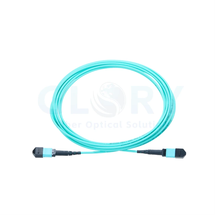
OM3 MPO to MPO Patch Cord
Extend an existing OM3 cabling plan through the rack with Glory Optical's OM3 MPO to MPO Patch Cord. A single 3.0 mm cord carries twelve 50/125 μm multimode fibers over a 1 m patching route. The specified build combines pinless UPC connectors, a crossed Type B fiber arrangement and a plenum OFNP sheath for connections selected as part of the complete optical channel.
|
Aqua OM3 cable with capped connector ends; supplied configuration: twelve fibers, pinless UPC, crossed wiring. |
An OM3 Patch Lead for Cabinet Adds and ChangesExplore the cabling range / View MPO connection options Twelve optical paths in one cord · 1 m reach between patching points · 3.0 mm sheath Use this assembly where the planned channel calls for OM3 fiber and female UPC terminations. Check the port hardware before allocating the cord: its guide holes need a compatible pinned mating connector. |

OM3 Assembly Ratings
| Rated item | OM3 configuration |
|---|---|
| Product name | OM3 MPO to MPO Patch Cord |
| Cable length | 1 m (3 ft nominal) |
| Connector A | US Conec MTP®-12 Elite female (non-pinned) |
| Connector B | US Conec MTP®-12 Elite female (non-pinned) |
| Fiber mode / core and cladding | OM3 multimode, 50/125 μm |
| Fiber count | 12 fibers |
| Polish | UPC to UPC |
| Polarity | Type B, crossed |
| Cable jacket | Plenum (OFNP) |
| Glass fiber | Bend-insensitive fiber |
| Cable outside diameter | 3.0 mm |
| Wavelengths | 850 / 1300 nm |
| Insertion loss | ≤0.35 dB maximum; 0.15 dB typical |
| Return loss | ≥27 dB |
| Fiber attenuation at 850 nm | ≤2.3 dB/km |
| Fiber attenuation at 1300 nm | ≤0.6 dB/km |
| Minimum bend radius - optical fiber | 7.5 mm |
| Minimum bend radius - finished cable | 20D dynamic / 10D static; D = cable outside diameter |
| Connector durability | 500 mating cycles |
| Tensile strength | 90 N long term / 180 N short term |
| Operating temperature | −10 to +60°C (14 to 140°F) |
| Storage temperature | −10 to +70°C (14 to 158°F) |
Allow a radius of at least 60 mm while moving the finished cord and 30 mm once it is stationary. These routing values follow 20D and 10D with D = 3.0 mm. The separate 7.5 mm glass-fiber rating is not the bend allowance for the jacketed assembly.
Inside the Connector: Alignment and Retention
|
US Conec reference exploded view. Alternative pin hardware is shown together; the ordered OM3 ends are pinless. |
Understand the Parts You HandleThe mating surface holds a row of twelve fiber positions in a multi-fiber ferrule. Behind it, the housing key establishes the insertion orientation and the latch retains the housing at the selected port. A spring-loaded internal stack supports the ferrule. In this female build, guide holes receive the pins from the opposite connector. The male hardware in the drawing illustrates another configuration, rather than additional pins supplied with the cord. At the cable exit, the crimp and boot support the transition into the sheath. Hold the connector body during removal, release its latch correctly and leave the dust cap in place until the interface is ready for inspection. |

| Part shown | What to check during use |
|---|---|
| Multi-fiber ferrule | Keep the twelve-position optical face free of contamination and damage. |
| Housing key and latch | Align the key with the port; release the retention mechanism before withdrawal. |
| Internal spring assembly | Maintains the spring-loaded ferrule arrangement inside the connector. |
| Guide-hole / guide-pin hardware | Female ends on this cable receive the pins of the mating interface; the drawing also includes male alternatives. |
| Rear crimp and strain-relief boot | Support the sheath transition without sharp turns or lateral connector loads. |
| Removable protective cap | Refit on unused ends; inspect again before making an optical connection. |
Trace Every Position Before Patching
|
FOA reference: a pinned ferrule engages the matching holes in a pinless ferrule through the adapter. |
Work from the Port Map, Then Choose the AdapterStart with the receptacle on the module or cassette. Record whether it has guide pins and confirm UPC polish. This lead has no pins at either end, so each connection requires the correct complementary interface. The cable crosses the fiber row: End A position n reaches End B position 13 − n. For example, A1 arrives at B12 and A6 arrives at B7. The Type B assembly uses key-up/key-up orientation. Follow the transmit and receive lanes through every cassette and adapter in the route. A correctly labeled cord alone does not establish channel polarity when additional components change the position order. |

| A position → B position | Remaining crossed pairs |
|---|---|
| 1 → 12; 2 → 11 | 3 → 10; 4 → 9 |
| 5 → 8; 6 → 7 | 7 → 6; 8 → 5 |
| 9 → 4; 10 → 3 | 11 → 2; 12 → 1 |
Where This Short OM3 Lead Fits
|
FOA modular-link example: cassette wiring and equipment leads must be chosen to complete the intended channel. |
Keep an Existing OM3 Cassette Route ConsistentFor a cassette-based installation, record the fiber grade on the installed link before adding a jumper. Choose the relevant panel and cassette arrangement with the required UPC mating hardware and documented rear-port wiring. Twelve fibers can serve six duplex paths through an appropriately wired fanout cassette. That path count describes a suitable cassette arrangement; the cord itself terminates in one multi-fiber connector per end. Check the duplex transmit/receive pairing after the complete route is assembled. |

|
NHLink rack-layout example, used to illustrate routing. The pictured assemblies are not a specification drawing for this cord. |
Patch Parallel Optics Within the CabinetMeasure the actual route around cable managers, including the connector exits, before selecting the 1 m length. Leave enough access for the latch and adjacent ports, then secure the cord without crushing its sheath. An appropriately configured OM3 channel may connect 40G QSFP+ SR4 or 100G QSFP28 SR4 ports. These parallel interfaces use eight active fibers within a twelve-position connection. Confirm the exact transceiver specification, lane map and total channel attenuation before assigning a speed or distance. A fiber grade on one patch lead does not describe the whole installed channel. Share the existing link details when reviewing an OM3 data center cabling plan. |

Bring the OM3 Channel into Service
Check the End Faces Before Measuring Loss
Uncap one connection at a time. Examine both optical faces, clean when needed and inspect again before mating. Establish continuity for the full twelve-position array, including positions that the selected transceiver does not use, and compare the measured route with the crossed wiring schedule.
Use multimode reference leads and a test method agreed for the order. Accept insertion loss against the 0.35 dB maximum and return loss against the 27 dB minimum; 0.15 dB is a typical insertion-loss value, not a stricter maximum. Budget separately for the other connectors, passive devices and installed fiber in the channel.
Leave Service Access at Each Connector
Place the service loop where it will remain accessible after the cabinet is populated. Avoid a tight bend immediately behind the boot and do not use the connector as a cable tie-down point. The mechanical tensile ratings are 90 N for long-term loading and 180 N for short-term loading; they are not pulling targets during connector handling.
Build Out the Cabling Path
| System element | Decision to make |
|---|---|
| Patch-panel hardware | Choose mounting space and cassette organization, then document each rear-port interface. |
| OM3 MPO/LC fanout options | Review the linked OM3 example for LC distribution; select the correct end genders and lane-to-duplex wiring for your equipment. |
| Cabling design support | Provide the installed route, optics and passive components for an end-to-end channel review. |
Prepare an OM3 Cable Schedule
| Schedule field | Detail to include with the inquiry |
|---|---|
| Baseline build | OM3 50/125 μm; twelve fibers; 1 m length; 3.0 mm OD; OFNP sheath. |
| Mating ports | Identify the pinned UPC interface at each end and attach its port drawing where available. |
| Fiber routing | Specify Type B crossing and identify any cassette that changes the position sequence. |
| Inspection scope | Agree multimode measurement references and records for IL ≤0.35 dB maximum and RL ≥27 dB. |
| Installed channel | List the transceiver models, existing OM3 link length and every passive connection. |
| Supply details | State quantities, port labels, packaging format and requested shipment date. |
| Requested variations | Submit a separate configuration for any other length, connector gender, polarity or jacket. |
Submit the port-to-port schedule with quantities and identification labels. Add the cassette drawing or optical-module model so the requested assembly can be checked against the intended connection. Contact Glory Optical for help completing the order details.
Ask for OM3 Pricing Explore More Cabling
MTP® is the registered trademark of US Conec Ltd. The reference drawings explain general connector and cabling principles; use the approved configuration record for the delivered assembly.
Project Support from Glory Optical
|
Glory Optical manufacturing location in Ningbo, China |
Glory OpticalEstablished 2008 · Based in Ningbo · Fiber connectivity and OEM/ODM supply Glory Optical supplies passive optical connectivity for network construction and maintenance. Contractors, distributors, service providers and equipment brands can source patch cords and MTP/MPO assemblies alongside adapters, pigtails, PLC splitters, fiber enclosures, splice closures and installation accessories from Ningbo Glory Optical Communication Co., Ltd. From Sample Review to Repeat OrdersA project can begin with the required interface, a drawing or an approved sample. Depending on the product family, our manufacturing work includes mold development, enclosure production, component assembly and cable assembly. Confirm labels, brand presentation, packaging and sample acceptance before the repeat-order specification is released. |

See Our Wider Product Testing Work
These videos present enclosure tests from other Glory Optical product lines. They provide a view of our wider work; acceptance of an OM3 patch cord instead relies on the agreed end-face, continuity, polarity and optical-loss checks for that assembly.
Enclosure Water Spray Test |
Enclosure Seal Evaluation |
Enclosure Water Exposure Test |
Agree the Inspection Records in Advance
Define what accompanies the shipment while reviewing the sample: configuration sheet, drawing, labels and any applicable inspection records. For this connectorized cord, specify the required end-face checks and optical measurements, including the reference method. Documentation scope and packing details form part of the confirmed order.
Send the Details Needed for a Quotation
Tell us how many OM3 cords you need, the installation route and the mating equipment. Attach any port drawing and list the desired delivery, labeling and packaging details. Our team can then review the configuration and discuss samples or production supply.
Ask for OM3 Pricing | Write to Sales
Email: sales@gloryoptic.com
Hot Tags: om3 mpo to mpo patch cord, China om3 mpo to mpo patch cord manufacturers, suppliers, factory, data center cabling, data center fiber cabling, Mpo 12 Fiber Cable, mtp mpo, Mtp Mpo Fiber, Mtp Mpo Fiber Breakout Cable


