OM4 MPO-24 to 2×MPO-12 Breakout Cable
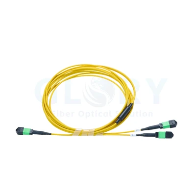
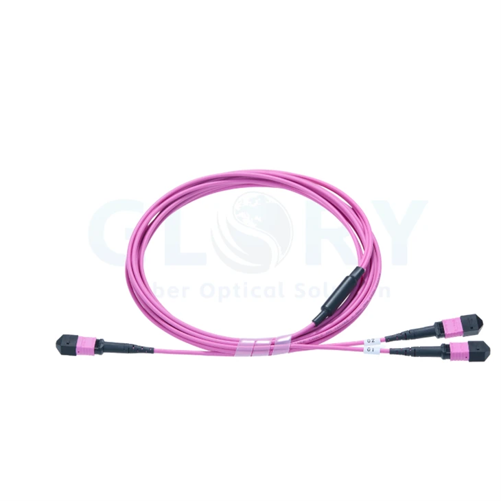
Bring an OM4 24-fiber connection into a Base-12 distribution plan with Glory Optical's MPO-24 to 2×MPO-12 breakout cable. The compact 1 m assembly presents a single 24-position female UPC connector at one end and a pair of 12-position female UPC connectors at the other. Twenty-four multimode fibers remain available across the two output groups.

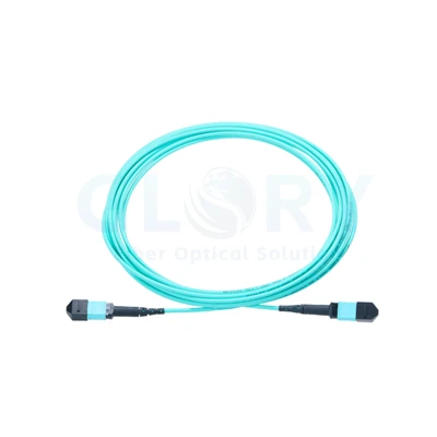
Connector detail for orientation. The ordered cable has three female UPC ends in a 24-to-two-12 layout; the pictured connector genders and colors are examples. |
Connect an OM4 Base-24 Port to Two Base-12 Groups1 m assembly · OM4 50/125 μm · 24 fibers · Type A routing · UPC female ends · OFNP sheath Allocate the two branches to the required distribution ports and keep their identifiers with the cabling record. A shared 24-fiber connection can then be documented as two separately accessible 12-fiber groups at the conversion point. |
Document the Common Port and Both Branches
| Connection point | Fiber group | Port information to confirm |
|---|---|---|
| Common end | 24 fibers in one female UPC connector | Identify the matching 24-fiber pinned receptacle. |
| Branch group 1 | 12 fibers in one female UPC connector | Record its destination port and mapping reference. |
| Branch group 2 | 12 fibers in one female UPC connector | Record the second destination and its mapping reference. |
The assembly changes the physical connection format while preserving the total fiber population. The two branch names above are planning labels; confirm actual production identifiers and every fiber-position assignment on the cable drawing. Type A must be assessed together with the other components in the intended channel.
OM4 Optical and Mechanical Ratings
| Rated item | Value for this build |
|---|---|
| Product name | OM4 MPO-24 to 2×MPO-12 Breakout Cable |
| Nominal length | 1 m (3 ft nominal) |
| Assembly topology | One 24-fiber MPO-compatible connector to two 12-fiber MPO-compatible connectors |
| Populated fibers | 24 fibers, arranged as two groups of 12 |
| Multimode fiber grade | OM4 50/125 μm |
| 24-fiber termination | US Conec MTP®-24 Elite female, non-pinned |
| 12-fiber terminations | 2 × US Conec MTP®-12 Elite female, non-pinned |
| Polish on all ends | UPC |
| Fiber routing type | Type A |
| Jacket | Plenum (OFNP) |
| Glass construction | Bend-insensitive fiber |
| Wavelengths | 850 / 1300 nm |
| Cable OD | 3.0 mm |
| Breakout section length | 0.5 m |
| Glass-fiber minimum bend radius | 7.5 mm |
| Finished-cable minimum bend radius | 20D dynamic / 10D static; D = cable outside diameter |
| Installation tensile rating | 66 N |
| Long-term / short-term tensile strength | 80 N / 240 N |
| Connector insertion loss | ≤0.35 dB maximum; 0.15 dB typical |
| Return loss - 24-fiber end | ≥20 dB |
| Return loss - 12-fiber ends | ≥27 dB |
| Fiber attenuation at 850 nm | ≤2.3 dB/km |
| Fiber attenuation at 1300 nm | ≤0.6 dB/km |
| Operating temperature | −10 to +60°C (14 to 140°F) |
| Storage temperature | −10 to +70°C (14 to 158°F) |
Return-loss acceptance differs by connector format: at least 20 dB at the 24-fiber end and 27 dB at each 12-fiber end. Keep these values separate when preparing the inspection sheet. The 0.15 dB insertion-loss value is typical; the specified maximum remains 0.35 dB.
What Holds the Multi-Fiber Interface Together

Component illustration with multiple connector variants. This build uses pinless female terminations at the common end and both branches. |
From the Optical Array to the Housing and BootThe optical ferrule brings a row or array of fiber positions to the connector face. Its surrounding housing locates the assembly at the selected port and provides the keyed orientation and release features used during servicing. Spring components support the ferrule inside the housing. The gender-specific parts shown are alternative arrangements; the selected female configuration has guide holes that work with the pins of the mating connector. Behind the internal stack, cable retention and the flexible boot support the exit from the connector. Give each branch its own service clearance so releasing one housing does not load the other termination. |
| Connector area | Point to review |
|---|---|
| Optical face | Correct UPC finish and the specified 24- or 12-fiber interface. |
| Alignment hardware | Pinless cable ends matched to the intended pinned counterparts. |
| Key and release housing | Orientation at the adapter plus space to operate the release. |
| Cable exit | A supported transition that leaves room for the finished-cable bend allowance. |
Match Female UPC Ends Throughout the Connection

Gender and alignment example. Use the technical schedule to establish UPC polish, fiber count and the required port configuration. |
Confirm the Interface Record Before Selecting AdaptersStart with the existing 24-fiber port and the two intended 12-fiber ports. For each, establish whether the mating side carries alignment pins, the supported connector format and its optical-face polish. The adapter retains and orients the housings, while the pin-and-hole combination aligns the ferrules. A matching shell alone does not establish the complete optical connection; review gender, orientation and UPC finish with the equipment or cassette drawing. Use the factory position map to check how the Type A assembly fits into the larger cabling arrangement. Keep this routing check distinct from the visual examination of the connector bodies. |
Use the Conversion Point in a Complete OM4 Channel

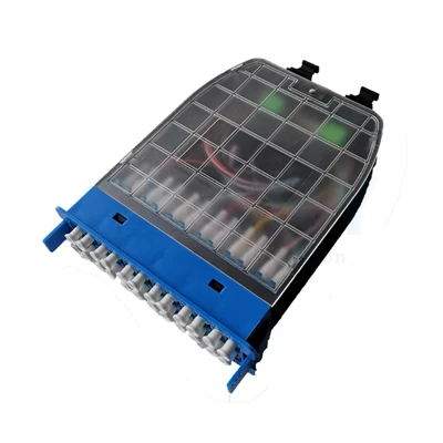
Structured-cabling illustration. Modules and downstream leads are separate selections; the diagram is not a drawing of the three-ended conversion assembly. |
Coordinate Distribution Modules with the Two Fiber GroupsAt a managed patching location, the two Base-12 groups can be assigned to compatible distribution interfaces. Select the fiber grade, port format and internal wiring of every passive module as part of the same OM4 design. Review the panel and cassette options for the rack arrangement, then define their populated optical interfaces. The enclosure capacity and the module's actual fiber routing need separate confirmation. Where downstream duplex circuits are required, establish the pairing through the selected modules or leads. The conversion cord supplies the two 12-fiber connections; downstream hardware defines how those groups are presented to equipment. |

Passive channel example. Port speeds, optical modules and active-fiber positions depend on the equipment selected for the project. |
Check Active Fibers and Loss Before Assigning Parallel OpticsParallel multimode equipment can use selected positions within a 12-fiber interface. Compatibility requires the appropriate optics, pin arrangement, polarity and complete lane map. The 24 populated fibers in this assembly do not automatically define the number of active channels at an optical module. Plan the installed OM4 distance and the loss of all mated interfaces and passive devices together. The nominal 1 m length describes this conversion segment; the chosen optics determine the allowable channel reach and operating mode. For route planning and an equipment-interface review, see our data center fiber design support. |
Reserve Space for the Branch Transition
Lay out the common side, the transition and both connector exits before fixing the cable position. The stated breakout section is 0.5 m within a nominal 1 m assembly. Agree the measurement points on the drawing rather than assuming the two values should be added.
Use the 3.0 mm finished-cable diameter when calculating bends: 20D gives a 60 mm moving radius and 10D gives a 30 mm stationary radius. The 7.5 mm glass-fiber figure applies to the fiber itself. Route the jacketed assembly to its finished-cable limits and avoid a tight turn immediately behind a boot.
Support the cable during handling and keep installation tension within the 66 N rating. Long-term and short-term tensile-strength values are 80 N and 240 N respectively; they describe different loading conditions. Do not transfer a pulling load through the release mechanism or across an adjacent branch.
Commission the Conversion with an OM4 Test Record
Establish Clean Interfaces and Traceable Position Labels
Inspect all three ferrules and their mating faces using suitable multi-fiber tools. Clean where needed and check again before connection. Assign identifiers to the 24-fiber end and both 12-fiber ends so the same labels appear on the drawing, continuity record and loss report.
Measure the Connector Formats Against Their Own Limits
Verify all 24 optical paths against the approved routing map. Use appropriate multimode reference leads and an agreed test procedure for optical measurements. Identify the test wavelengths and reference setup in the report so results can be evaluated consistently.
Apply maximum insertion loss of 0.35 dB to the specified connector acceptance scope. Record return loss against the separate limits of 20 dB for MTP®-24 and 27 dB for MTP®-12. Include the remaining cabling components when calculating an installed channel budget; typical values are not substitutes for the agreed maximum limits.
Complete the Rack Connection with Matching Products
| Product or service | Configuration detail to provide |
|---|---|
| MTP/MPO assemblies | OM4 fiber, required end genders and the 24-to-two-12 wiring drawing. |
| MPO distribution hardware | Loaded module format, mounting plan and the complete optical route. |
| MPO/LC harness options | Review a separate downstream fanout when the design needs duplex connections; confirm fiber grade and pair mapping. |
Order the Build with Its Port and Drawing References
| Confirmation item | Detail for the order |
|---|---|
| Optical configuration | OM4 50/125 μm, 24 fibers, Type A, female UPC interfaces. |
| End formats | One MTP®-24 common end and two MTP®-12 branches. |
| Physical schedule | 1 m nominal length, 0.5 m breakout section, 3.0 mm OD and OFNP jacket. |
| Port documentation | Counterpart gender, adapter keying, branch identifiers and approved position map. |
| Quality records | Multimode reference procedure and separate 24-fiber / 12-fiber return-loss criteria. |
| Supply requirements | Quantities, production labels, packaging, inspection documents and delivery target. |
Send the intended common port and both branch destinations to our technical sales team. Include a rack sketch or interface drawing where available so the configuration, sample and documentation requirements can be reviewed together.
Ask for an OM4 Breakout Cable Quotation Explore the Cabling Portfolio
MTP® is a registered trademark of US Conec Ltd. The illustrations show connector and channel concepts. Supplied fiber routing, interfaces and dimensions follow the approved configuration record.
Glory Optical Supply for Fiber Projects
|
Glory Optical production facility, Ningbo, China |
A Ningbo-Based Passive Connectivity ManufacturerFounded in 2008 · Fiber assemblies and components · Project and OEM/ODM supply Network installation and maintenance require both the optical connection and the hardware around it. Glory Optical's product range covers terminated fiber assemblies, adapters, pigtails, splitters, enclosures and splice closures. We serve operators, equipment suppliers, contractors and distribution partners from Ningbo, China. Confirm the Build Before ProductionThe drawing or sample provides a starting point for the assembly specification. Confirm connector types, cable construction, wiring, labels and packing with the production requirement. Across different product families, our manufacturing work includes cable termination, component assembly, molding and tooling development; the applicable scope follows the selected item. |

Company Testing Demonstrations
These videos show water and sealing evaluations of enclosure products in the broader range. Optical acceptance for the OM4 conversion cable uses the checks agreed for that assembly, including end faces, continuity, fiber mapping and optical measurements. Confirm the required cable records with the order.
Water-Spray Test Demonstration |
Seal Test Demonstration |
Water-Resistance Test Demonstration |
Agree the Supporting Documentation
State which drawings, configuration sheets and applicable inspection results the receiving team needs. The same part definition should connect those records with the production labels and packing instructions. Agree how measurements are referenced and which connector limits apply before the documentation package is finalized.
Glory Optical Supply for Fiber Projects | OEM/ODM Supply Enquiries
Share the Interface and Supply Schedule
Provide the assembly quantities, the three mating ports and the proposed routing space. Add any sample, labeling or packaging requirement together with the desired delivery schedule. Our team can then discuss the practical configuration and supply details for the project.
Get Project Pricing | Email the Sales Team
Email: sales@gloryoptic.com
Hot Tags: om4 mpo-24 to 2×mpo-12 breakout cable, China om4 mpo-24 to 2×mpo-12 breakout cable manufacturers, suppliers, factory, data center cabling, data center fiber cabling, Mpo 12 Fiber Cable, mtp mpo, Mtp Mpo Fiber Breakout Cable, Mtp To Lc Breakout Cable