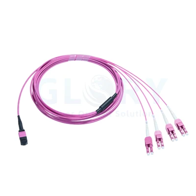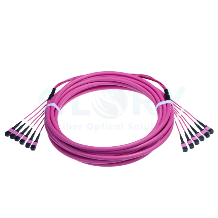
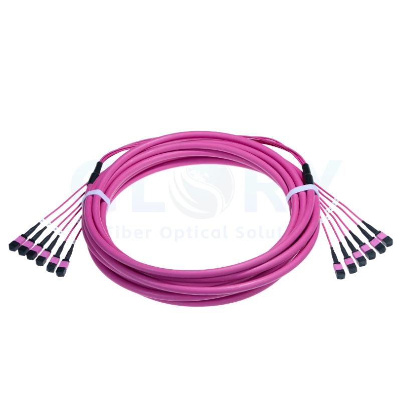
OM4 MPO Multi-Connector Trunk Cable
Bring multiple OM4 circuits through one pre-terminated route. This Glory Optical trunk combines a double-jacket cable with individually connectorized Base-12 units, allowing the termination areas to accommodate the selected capacity from 12 to 576 fibers. Specify the UPC connector gender for each end, choose the insertion-loss grade, then establish the required wiring and cable length.
Interface illustration only. Cable color, pin arrangement and the quantity of connectors are determined by the ordered OM4 build. |
One Route, Organized into 12-Fiber TerminationsOM4 50/125 μm · UPC mating · 12–576 fibers · two loss grades · double-jacket cable Allocate a connector group to each planned destination port. Higher fiber counts add more connectorized units at both ends while retaining a common main-cable pathway. Select OFNP or LSZH to suit the installation specification. Explore our passive cabling portfolio / Browse multi-fiber assemblies |
OM4 Assembly Data and Orderable Options
| Parameter | OM4 configuration |
|---|---|
| Product designation | OM4 MPO Multi-Connector Trunk Cable |
| Termination format | Base-12 trunk; connectorized 12-fiber units at each end |
| Optical fiber category | OM4 multimode, 50/125 μm |
| Available fiber populations | 12, 24, 36, 48, 72, 96, 144, 192, 216, 288, 432, 576 fibers |
| A-side termination | MTP®-12 Elite; male or female UPC |
| B-side termination | MTP®-12 Elite; male or female UPC |
| End-face geometry | UPC / UPC |
| Wiring selection | Type A, Type B or Type C |
| Assembly length | Custom length; establish the measurement points before ordering |
| Outer-jacket selection | OFNP (plenum) or LSZH |
| Protective construction | Two jacket layers |
| Trunk outside diameter | 3.6–21 mm across the configuration range |
| Individual branch diameter | 2.0 mm |
| Fanout-unit length | 0.84 m |
| Selectable insertion-loss limits | ≤0.20 dB or ≤0.35 dB; selected grade applies at both ends |
| Minimum return loss | 27 dB |
| Optical reference wavelengths | 850 nm and 1300 nm |
| 850 nm attenuation limit | 2.3 dB/km |
| 1300 nm attenuation limit | 0.6 dB/km |
| Fiber construction | Bend-insensitive multimode glass |
| Glass-fiber minimum radius | 7.5 mm |
| Cable routing radius | 20D during movement / 10D when installed; D = trunk OD |
| Sustained tensile-load range | 100–200 N; final value depends on construction |
| Temporary tensile-load range | 300–660 N; final value depends on construction |
| OFNP service temperature | −10 to +60°C (14 to 140°F) |
| LSZH service temperature | −10 to +70°C (14 to 158°F) |
| OFNP storage temperature | −10 to +70°C (14 to 158°F) |
| LSZH storage temperature | −20 to +70°C (−4 to 158°F) |
| Installation pulling sleeve | No pulling eye, A-side, B-side or both sides |
Diameter and tensile loads vary across the available builds. Confirm the individual cable's dimensions and ratings on its released part drawing. Each loss grade is an orderable connector limit; the two listed values do not represent typical and maximum results for one grade.
Select the Loss Grade before Closing the Channel Budget
Choose a maximum connector insertion loss of 0.20 dB or 0.35 dB for the assembly. The selected grade applies at both the A-side and B-side; connector gender remains a separate choice for each side. Record the grade on the purchase specification so optical results can be checked against the correct limit. The minimum connector return loss is 27 dB.
Evaluate the complete multimode path using its length, all mating interfaces and any modules or patch leads. The fiber attenuation limits are 2.3 dB/km at 850 nm and 0.6 dB/km at 1300 nm. Use the appropriate wavelength and test procedure for the intended equipment; the connector rating alone does not establish an application's permitted reach.
Turn Fiber Capacity into a Port Schedule
One Base-12 termination carries twelve fibers. Divide the selected total by twelve to obtain the number of connector groups on each side. A unique group identifier should follow that unit from the first termination area to the second, with the fiber-position correspondence captured in the wiring record.
| Cable capacity | Connector groups on side A | Connector groups on side B |
|---|---|---|
| 12 fibers | 1 × 12-fiber | 1 × 12-fiber |
| 24 fibers | 2 × 12-fiber | 2 × 12-fiber |
| 36 fibers | 3 × 12-fiber | 3 × 12-fiber |
| 48 fibers | 4 × 12-fiber | 4 × 12-fiber |
| 72 fibers | 6 × 12-fiber | 6 × 12-fiber |
| 96 fibers | 8 × 12-fiber | 8 × 12-fiber |
| 144 fibers | 12 × 12-fiber | 12 × 12-fiber |
| 192 fibers | 16 × 12-fiber | 16 × 12-fiber |
| 216 fibers | 18 × 12-fiber | 18 × 12-fiber |
| 288 fibers | 24 × 12-fiber | 24 × 12-fiber |
| 432 fibers | 36 × 12-fiber | 36 × 12-fiber |
| 576 fibers | 48 × 12-fiber | 48 × 12-fiber |
A 96-fiber build provides eight groups per side; a 288-fiber build provides twenty-four. Reserve enough panel positions and management space for the chosen quantity. For the smallest 12-fiber selection, the assembly has a single multi-fiber connector at either end.
Define the UPC Interface at Every Connection

General mating geometry. Check the ordered UPC interfaces and gender against the actual ports used in the installation. |
Separate Gender, Key Orientation and Fiber RoutingGuide pins identify a male interface; the complementary female interface has guide holes. Review the mating partner for each end rather than choosing gender from the cable name or the housing color. Specify UPC at both sides of this OM4 assembly. Confirm the adapter key arrangement and connector access before finalizing the end details, particularly where several grouped units terminate next to one another. Type A, Type B and Type C are selectable routing arrangements. Choose the map that completes the required transmit-to-receive paths through the connected equipment and passive hardware, and retain that map with the cable identifier. |
From the Shared Cable to the Connector Ferrule

Component overview with alternative pin hardware. It illustrates connector construction rather than the exact parts list of the finished trunk. |
Provide Space for the Branches and Release HousingsInside each termination, the ferrule locates the optical fibers while spring and retention components support the mating assembly. The keyed housing positions the connector at its port; the boot manages the transition to the branch cable. The trunk divides into 2.0 mm branch units with a stated fanout length of 0.84 m. Locate the transition so those units reach their assigned ports without placing tension on the connector boots. Service access matters when the group count increases. Arrange identification and branch routing so a technician can read a label, inspect the interface and operate the release without disturbing adjacent circuits. |
| Assembly zone | Detail to establish |
|---|---|
| Main route | Selected outside diameter, support positions and space for a two-layer jacket. |
| Branch transition | Installed position and reach of the 0.84 m fanout units. |
| Connector field | Required number of UPC ports and room for release operation. |
| Identification points | Cable identifier, group labels and an agreed numbering direction. |
| Pulling protection | Sleeve location and the approved attachment method for installation. |
Plan the Distribution Route around the Optical Circuit

Modular distribution example. The selected modules must support the OM4 fiber category and the specified trunk interfaces. |
Distribute Capacity through Compatible ModulesA connector group can feed a suitable distribution module when its gender, UPC geometry and internal position map match the design. Map the equipment-side duplex ports to the trunk fibers before assigning module labels. Review MPO patch-panel options together with the module population. Include branch storage, rear connector access and the total group quantity in the cabinet plan. Duplex equipment connections require the appropriate modules or separately specified MPO-to-LC breakout assemblies. Confirm their OM4 configuration and pairing as part of the same circuit schedule. |

Optical-path illustration. Active-fiber usage, distance and data rate follow the chosen multimode equipment and channel design. |
Check Fiber Usage before Assigning Parallel LinksFor equipment with multi-fiber optical ports, verify the exact connector, pin arrangement and occupied fiber positions. A twelve-fiber cable group does not mean every fiber is used by every optical interface. Trace the proposed channel through each patching point. Account for the selected loss grades, cable attenuation and the other passive components when checking it against the equipment's optical budget. Our data center connectivity team can review the proposed path using the equipment list, group schedule and measured route. |
Route the Finished Cable to Its Own Bend Limits
The 7.5 mm minimum radius describes the glass fiber. For the jacketed assembly, allow 20 times the main-cable diameter during movement and 10 times that diameter once installed. Determine D from the ordered construction, whose trunk diameter lies within the 3.6–21 mm family range.
Plan the route length from the actual termination locations. Preset selections include 2, 3, 5, 10, 15, 20, 25 and 30 m, with custom length available. Mark the overall-length reference points and the fanout transitions on the drawing so installation staff can position the cable consistently.
Pulling protection is selectable at the A-side, B-side or both sides; a build without a pulling eye is also available. Check that the pathway accommodates the protected connector bundle and establish how force transfers to the assembly during the pull.
Construction-dependent tensile ranges are 100–200 N for sustained loading and 300–660 N for short-term loading. Obtain the specific build's allowable values before installation, and secure the cable at its intended supports after routing.
Use the Temperature Range for the Selected Jacket
| Jacket material option | In service | In storage |
|---|---|---|
| OFNP / plenum | −10 to +60°C | −10 to +70°C |
| LSZH | −10 to +70°C | −20 to +70°C |
Include the required jacket type in the order rather than selecting it from the illustration. Match the material choice to the project's installation requirements, then use the corresponding temperature limits for handling, storage and service planning.
Accept the Assembly by Group and Loss Grade
Identify, Inspect and Trace
At receipt, reconcile the total fiber count and connector quantities with the schedule. Check the end labels and gender, inspect the optical faces and verify continuity against the approved position map. Clean and re-inspect an interface when its condition requires it before making the connection.
Retain Multimode Measurement Details
Define the multimode launch conditions, reference leads, measurement wavelengths and acceptance method before testing. Associate each result with its cable, connector group and fiber position, and compare it with the ordered insertion-loss grade.
Keep component measurements and the installed-channel assessment in the project records. The latter includes the complete routed length and all passive connections that the operating signal will encounter.
Coordinate the Remaining Passive Components
| Glory product family | Information needed for compatibility |
|---|---|
| Multi-fiber cable systems | OM4 glass, UPC faces, pin configuration and the specified fiber map. |
| Distribution panels | Port allocation, module selection and rear branch-management capacity. |
| Equipment fanout cables | Matched multimode interfaces and documented duplex fiber pairing. |
Send the OM4 Build Requirements for Review
| Order field | Required entry |
|---|---|
| Capacity and grouping | Total OM4 fibers, connector-group count and endpoint allocation. |
| Connector definitions | A-side and B-side gender, UPC interface and the shared 0.20 or 0.35 dB grade. |
| Optical routing | Chosen polarity and the drawing that defines the fiber-position correspondence. |
| Physical dimensions | Overall length, measurement convention, branch reach and route constraints. |
| Material and pulling method | OFNP or LSZH; pulling-eye location and construction-specific mechanical limits. |
| Delivery record | Identifiers, quantities, test-document requirements and packing instructions. |
Use the project enquiry form to share the proposed circuit and cable requirements, or reach our sales and engineering contacts with the drawing. A reviewed configuration provides the basis for quotation, sample preparation and production documentation.
Discuss This OM4 Configuration See Other Cabling Products
MTP® is a registered trademark of US Conec Ltd. The approved part specification defines the delivered assembly; the accompanying illustrations describe general interfaces and applications.
Glory Optical: Cable Assemblies and Project Support
|
Our Ningbo optical connectivity facility |
Our Optical Connectivity OperationEstablished in 2008 · Fiber assemblies and components · Custom manufacturing enquiries From Ningbo, China, Glory Optical supplies passive fiber connectivity to customers building and maintaining communications networks. Our range covers cable assemblies, optical adapters, pigtails and splitters, alongside termination boxes and splice enclosures. We work with distribution businesses, network operators, installation contractors and equipment customers on standard supply and custom requirements. From Configuration Review to ProductionAn OM4 trunk enquiry starts with the connection requirements: how many fibers, which ports and what routing map. Once the assembly drawing and sample details are agreed, they guide the applicable termination and assembly work. Customers requiring a custom product can also discuss component, enclosure and mold-development activities relevant to their project. |

Examples from Our Enclosure Evaluations
These demonstrations show evaluations of fiber enclosures and closures. Cable acceptance uses the checks agreed for the particular trunk, including optical-face condition, mapping and loss measurement. State the required cable test scope in the order documents so the shipment records answer the project's receiving requirements.
Spray-Test Demonstration |
Seal-Test Demonstration |
Water-Test Demonstration |
Records for Your Receiving and Installation Teams
Agree the document set while reviewing the build. It may include the approved dimensional drawing, label schedule and the specified optical results. Use consistent cable and group identifiers across those records so receiving staff and installers can reconcile a measurement with the physical termination.
Glory Optical: Cable Assemblies and Project Support | Discuss an OEM/ODM Requirement
Describe the Connection You Need
Tell us the fiber capacity, intended route and mating interfaces, together with the selected connector loss grade. Include jacket choice, labeling, installation protection and order quantities. Those details help our team develop a usable assembly specification and discuss sampling, quotation and delivery with you.
Ask for a Configuration Quote | Write to Our Product Team
Email: sales@gloryoptic.com
Hot Tags: om4 mpo multi-connector trunk cable, China om4 mpo multi-connector trunk cable manufacturers, suppliers, factory, data center cabling, Mpo 12 Fiber Cable, mtp mpo, Mtp Mpo Fiber, Mtp Mpo Fiber Breakout Cable, Mtp To Lc Breakout Cable