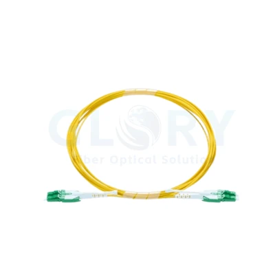
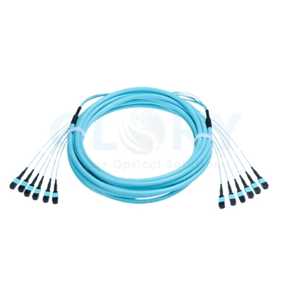
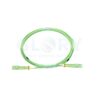
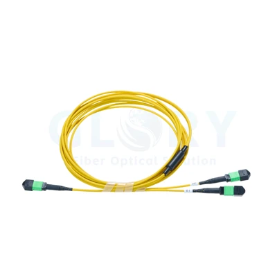
A Direct Multi-Fiber Lead with One Plug at Each End

Shown: aqua MTP-marked housings and gray protective caps on a magenta direct-connect cord. |
MTP to MTP Fiber Patch Cord (Magenta)Connect two matching multi-fiber interfaces through a single cable run. The illustrated cord has one compact MTP-marked plug at either end, carrying the optical paths together between the two termination points. Use this direct format between suitable distribution hardware or equipment interfaces. Select the fiber population and position map with the receiving ports so the assembled cord fits the intended connection. |
Identify the Grip, Transition and End-Face Protection
| Visible part | Role during handling |
|---|---|
| Aqua connector housing | Provides the connector body and handling surface at the mating interface |
| Black rear boot | Supports the transition between the connector assembly and cable |
| Gray removable cap | Covers the unmated end face during storage and handling |
The caps remain fitted while a connection is waiting to be made. Remove the cap for inspection and mating, and protect an exposed connector during work. Keep the cable supported so the rear boot is not carrying the weight of the route.
Choose Each Cable End against Its Receiving Interface
Check the connector population, pinning and polish at both receiving points. A mating connection requires compatible pinned and non-pinned interfaces. A female-to-female cable is one suitable arrangement when both receiving interfaces provide the mating pins; other port arrangements require a corresponding cable definition.
Keep the cable's position map with those interface details. The gender describes the alignment-pin arrangement, while the wiring map describes where the individual optical paths arrive. Both belong in the connection specification.
Review the MPO distribution panel range and multi-fiber connection products with the intended port pair.
A Twelve-Fiber OM4 Configuration for Quotation
Reference build only: the twelve-fiber OM4 profile below comes from a comparable published jumper configuration. The photograph establishes the MTP markings and physical appearance; fiber count, grade, pinning, polish, polarity, length and jacket classification must be confirmed for the supplied cord.
| Configuration field | Pictured detail or quotation example |
|---|---|
| Product designation | MTP to MTP Fiber Patch Cord (Magenta) |
| Visible end arrangement | One MTP-marked multi-fiber connector at each end |
| Pictured finish | Magenta cable, aqua housings, gray caps and black boots |
| Reference fiber build | 12 fibers, OM4 multimode, 50/125 µm |
| Reference connector interfaces | MTP-12 / UPC at both ends |
| Reference pinning | Female to female, non-pinned; check both receiving interfaces |
| Reference position mapping | Type B, subject to the approved end-to-end wiring plan |
| Reference jacket classification | Plenum (OFNP) |
| Reference finished length | 1 m example; request the length required for the route |
| Connector loss selection target | Insertion loss ≤0.35 dB under the agreed connector evaluation |
| Additional optical criteria | Establish return loss and test wavelengths for the selected build |
| Mechanical data to establish | Actual outside diameter, bend radius and installation limits |
Use the connector target in its agreed test scope. Include the cable segment and other installed interfaces when assessing the complete optical channel. The actual port optics and channel design determine supported operation.
Prepare the Multi-Fiber Contact before Connection
Inspect the contact surface with equipment suitable for a multi-fiber connector and its pinning. Select the corresponding cleaning method when cleaning is required, then inspect again before mating. A fitted storage cap protects the end during handling but does not establish the condition of the contact surface.
During acceptance, check every populated fiber against the approved position map. Retain the continuity and optical results with the cord identifier so an interface change can be traced to the tested connection record.
Send the Two Port Definitions with the Cable Requirement
Provide the receiving interfaces, required populated fibers, fiber grade and wiring map. Add the route length, jacket classification, cord labels and quantity. Include any connector envelope or access restrictions at the two ports so the physical version can be reviewed with the optical definition.
Request Magenta MTP Cord Details Discuss the mating interfaces
For the wider installation, explore data center cable products or discuss a rack connection plan.
Keep the Accepted Interface Definition with the Order

Ningbo manufacturing site · Glory Optical. |
Review the Cord Sample and Required DocumentationOur Ningbo operation, established in 2008, supports passive optical connectivity projects. Share the two port descriptions and cable schedule when reviewing this assembly. Agree the sample version, cord identification and inspection records before the supply specification is finalized. Glory Optical company details · Discuss OEM assembly requirements |
Enclosure Evaluation Videos from Our Product Range
These clips show fiber boxes and splice closures. Acceptance of this patch cord should use its own agreed interface, continuity and optical checks.
Water Spray Evaluation |
Seal Performance Evaluation |
Water Resistance Evaluation |
Hot Tags: om4 mtp to mtp fiber patch cord, China om4 mtp to mtp fiber patch cord manufacturers, suppliers, factory, data center cabling, data center fiber cabling, Mpo 12 Fiber Cable, mtp mpo, Mtp Mpo Fiber, Mtp To Lc Breakout Cable