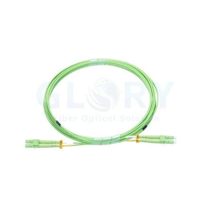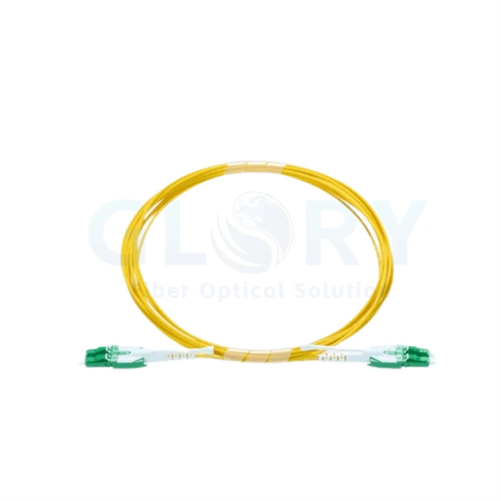
Yellow Duplex Cord with Green LC Housings

The pictured version combines green paired LC housings with white pull tabs and a yellow common cord. |
LC to LC Uniboot Duplex Patch Cord with Pull TabsA duplex LC pair terminates each end of this uniboot-style cord. The shared cable entry brings the two optical paths into one jacket, while the white tabs provide an accessible handling point beside the connector pair. Use this format for organized patching between duplex optical interfaces. The paired housing keeps the two LC positions together during connection work, and the common cord follows a single route through the cable manager. |
Specify the Mating Polish for an APC Build
For a single-mode APC version, define LC/APC at both cable ends and match each receiving interface to that polish. An APC ferrule has an angled contact surface; the reference design uses an 8° angle. The optical path and mating geometry need to be specified together when selecting the assembly.
Read the interface description on the equipment or adapter documentation. Green housings can help identify a proposed APC variant, but the confirmed connector specification establishes its polish. Keep the matching end-face type in the purchase description as well as the installation record.
Our connection-component range and panel options can be reviewed with the intended mating interfaces.
Use Separate Criteria for Forward Loss and Reflection
| Criterion | What to specify for the APC option |
|---|---|
| Insertion loss | A ≤0.30 dB selection target describes forward optical loss under the agreed connector test. |
| Return loss | A ≥60 dB selection target describes reflected power for the proposed single-mode APC termination. |
These criteria answer different optical questions. Include the measurement scope and test wavelengths in the acceptance requirement. The complete link also includes the fiber segment and any additional connections between the transmitter and receiver.
Keep the accepted results with the selected fiber and termination details. This provides a useful reference when a patching change introduces an unexpected loss or reflection result.
Cable and Connector Options for the Yellow Version
Reference configuration: the single-mode APC data and 2.0 mm cord below are selection starting points from a comparable uniboot family. The photograph identifies the mechanical style; its fiber grade, polish, jacket rating and exact mechanism still require confirmation.
| Selection field | Pictured feature or quotation starting point |
|---|---|
| Product title | LC to LC Uniboot Duplex Patch Cord with Pull Tabs |
| Termination layout | Duplex LC uniboot at both ends |
| Optical paths in the reference design | 2 fibers within one round cord |
| Pictured appearance | Yellow sheath, green connector housings and white pull tabs |
| Single-mode option for quotation | LC/APC at both ends; confirm the actual fiber specification |
| Cable-size starting point | 2.0 mm nominal round duplex |
| APC angle reference | 8° for the selected APC termination |
| Insertion-loss target | ≤0.30 dB; establish the connector evaluation scope |
| APC return-loss target | ≥60 dB for the selected single-mode APC build |
| Material and rating enquiry | PVC / OFNR, LSZH or OFNP as required by the selected construction |
| Finished length | Custom requirement with an agreed connector-to-connector measurement |
| Polarity and release mechanism | Specify the two fiber paths; demonstrate any polarity-change feature on the actual version |
Choose the jacket against the installation requirements. State the required material and fire classification explicitly, then confirm them for the finished cable. Include the permitted bend radius for that construction when laying out the route.
Keep the Release Point Reachable during Patching
Support the cable as the connector is seated, and check that the selected tab can operate beside the neighboring plugs. Keep the cord clear of a moving door or cable-management arm. Use the connector's release control for removal so the pull is applied through its intended handling point.
For an approval sample, check the housing and tab style in the actual port arrangement. If polarity adjustment is required, include a demonstration of that mechanism in the sample review and record the final two-fiber orientation.
Request a Cord Defined by Its Optical Interfaces
Send the receiving port descriptions, required fiber grade, end-face polish, finished length and quantity. Add the jacket classification and the illustrated green-housing/tab style. These details allow the quotation to describe both the optical connection and the physical cord that will be handled at the panel.
Request the Yellow Uniboot Version Contact Glory for configuration review
Find further fiber patch cord formats or discuss the wider route in a cabling layout review.
Discuss the Required Cord with Glory Optical

Ningbo, China · Glory Optical manufacturing location. |
Combine the Optical Description with a Physical SampleOur Ningbo business has served optical-connectivity projects since 2008. When discussing this cord, provide the interface description together with the preferred housing, cable and tab details. A sample can help establish the physical version before the specifications for identification, inspection and packing are finalized. |
Examples from Our Enclosure Product Evaluations
The following videos feature boxes and splice closures. Inspection of this patch cord should follow its agreed connector, continuity and optical criteria.
Water spray on a distribution box |
Sealing assessment of a splice closure |
Water check on a splice enclosure |
Hot Tags: lc to lc uniboot duplex patch cord with pull tabs, China lc to lc uniboot duplex patch cord with pull tabs manufacturers, suppliers, factory