An OM4 Backbone with Six MPO Interfaces per End

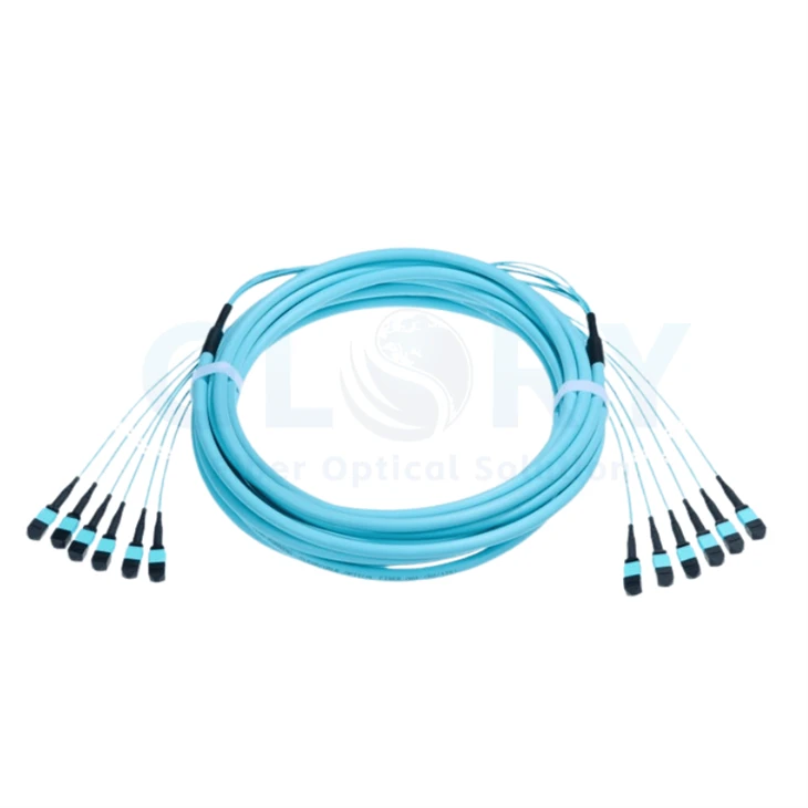
Aqua common jacket marked OM4 (50/125), with six MPO-format leads at each end. |
OM4 MPO Multi-Connector Trunk CableCarry multiple optical groups through a common trunk and distribute the MPO interfaces at the two termination points. The illustrated assembly combines a substantial aqua main cable with slender end leads, black transition protection and individually capped connector housings. The jacket marking identifies the pictured OM4 50/125 format. This multi-connector arrangement is suited to rack-to-rack or distribution-enclosure routes where several MPO interfaces share a common backbone path. |
Define Capacity from the Populated Fiber Positions
Connector quantity and fiber population are separate fields in the assembly definition. For a six-unit trunk, state how many positions are populated inside each MPO interface, then calculate the total. The examples below show the arithmetic for two possible order definitions; the photographed ferrule population remains to be confirmed.
| Example configuration | Calculation | Total optical fibers |
|---|---|---|
| Six fully populated 12-position units | 6 × 12 fibers | 72 fibers |
| Six fully populated 24-position units | 6 × 24 fibers | 144 fibers |
Use the selected population when choosing the MPO distribution hardware. Reserve capacity and port assignments against that definition so the cable schedule, adapter field and acceptance record describe the same build.
Preserve the Group Route and the Fiber Map
Identify Which Optical Group Reaches Each Landing Point
Give each end lead a durable unit identifier and relate it to the receiving adapter position. Record the correspondence between the two ends before the trunk is installed. This allows an installer to locate a group from either enclosure while keeping its shared-cable identity intact.
Set the Position Order inside Each MPO Interface
The fiber-position relationship within a connector determines how that optical group passes through the cabling system. Define the required polarity with the connected equipment and any cassettes or adapters. Review pinning and connector orientation alongside the position map, especially when the two landing points use different hardware.
Keep these two records together in a backbone planning review: the group route identifies the optical unit, and the position map defines its individual fiber paths.
Configuration Data for the Aqua OM4 Trunk
Configuration status: OM4 50/125 jacket marking and six connectors at each end are visible in the supplied photograph. The 72-fiber build, dimensions and performance figures below are quotation references from a comparable trunk family. Approve the actual population, connector details and limits for the supplied version.
| Assembly field | Identification or quotation reference |
|---|---|
| Product | OM4 MPO Multi-Connector Trunk Cable |
| Fiber identification on the jacket | OM4 multimode, 50/125 µm |
| Visible connector arrangement | 6 MPO-format connectors at End A; 6 at End B |
| Reference fiber population | 72 fibers when all 6 units contain 12 populated positions |
| Reference optical interface | MPO-12 / UPC; agree the pinning at both ends |
| Capacity and mapping record | Specify populated positions, unit sequence and internal fiber map |
| Polarity options for quotation | Type A, B or C, selected for the complete cabling design |
| Main-jacket choices | LSZH or OFNP, subject to the selected build and installation requirements |
| Reference trunk diameter | 12.7 mm nominal for a comparable six-bundle construction |
| Low-loss selection benchmark | Insertion loss ≤0.35 dB; confirm the supplied connector grade |
| Multimode reflection benchmark | Return loss ≥20 dB |
| Family operating-temperature reference | −20 to +70°C |
| Family storage-temperature reference | −40 to +85°C |
| Dimensions to order | Finished length and both end fanout lengths from agreed datum points |
Apply the connector loss criterion to the agreed measurement scope. Assess the complete installed path using its length and all intervening connections. Obtain the bend-radius and pulling limits for the finished cable construction before installation.
Allocate Space for Both Fanout Zones
At each enclosure, allow room for the common cable to enter, for the transition to be secured and for six leads to reach their assigned adapter locations. Measure this envelope with the enclosure in its normal working position, including any tray movement and access needed to inspect a connector.
Protect the end group during handling and install the specified strain relief on the trunk. Dress the leads into the adapter field after the main cable is supported. Retain enough service allowance to work on an individual interface without loading the neighboring plugs.
Use One Assembly Record across Receiving and Service
Provide the two enclosure locations, route measurement, selected fiber population and MPO interface drawing when requesting a build. Add the fanout dimensions, material class, identification format, required optical records and quantity. Keep the accepted drawing with the cable identifier so later changes can be traced to the original assembly.
Request the OM4 Trunk Configuration Speak with Glory about the route
Explore MPO connection products and the data center cabling portfolio for the other parts of the backbone.
Build the Supply Specification around the Accepted Trunk

Glory Optical production base in Ningbo. |
Coordinate the Cable Definition with Our Manufacturing TeamGlory Optical has operated in Ningbo since 2008. For a multi-interface backbone project, bring the enclosure layout and the proposed cable record to our team. Discuss how the construction, identification and inspection documents should accompany the order, including any requirements for repeat supply. |
Enclosure Testing from the Wider Product Range
The footage below concerns boxes and splice closures. For this trunk assembly, agree the continuity, interface-mapping and optical checks in its own acceptance record.
Spray evaluation of a fiber box |
Seal evaluation of a closure |
Water exposure of an enclosure |
Hot Tags: multi-connector mpo trunk cable, China multi-connector mpo trunk cable manufacturers, suppliers, factory