Four LC Pairs at the End of a Shared Lead

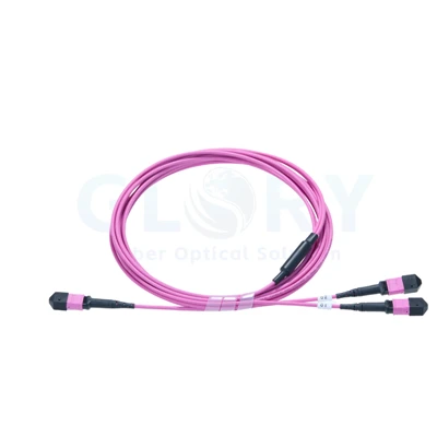
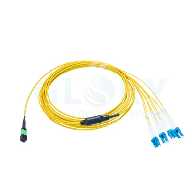
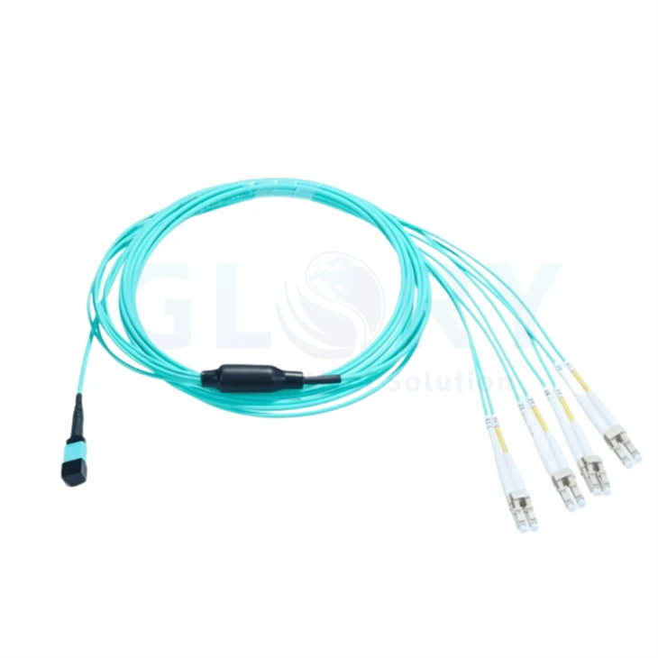
Shown: one capped MPO-format end, black transition and four conventional LC pairs. |
MPO to 4 LC Duplex Breakout CableBring the optical paths to one MPO-format connector, then present them as four accessible duplex LC connections. Each LC pair has two separate boots, so the final connections can be dressed toward different ports after the common cable reaches the equipment area. The aqua lead and black transition separate the shared route from the LC fanout. This conventional duplex version suits installations that use paired LC connectors with individual strain-relief boots. |
Place the Transition Where the Destinations Divide
Run the common lead through the main cable manager and let the fanout begin beside the destination group. Placing the transition too far back consumes branch reach; placing it inside the port row can leave the transition resting on connectors. Support the main lead before dressing the individual legs.
Measure each route from the proposed transition position to its LC port, including the service loop and the path through the manager. Keep the transition supported while connecting one pair at a time. Allow the remaining branches to rest without their weight pulling on a seated connector.
A rack connection layout and the selected distribution panel help define where the shared lead should end and the individual legs should begin.
Give Every Duplex Pair a Destination Identity
Use a pair label that appears on both the cable schedule and the receiving port record. The examples A–D illustrate a planning schedule. Replace the destination entries and label format with the approved project identifiers.
| Example pair label | Two LC positions | Destination to enter |
|---|---|---|
| A | A1 / A2 | First port or adapter pair |
| B | B1 / B2 | Second port or adapter pair |
| C | C1 / C2 | Third port or adapter pair |
| D | D1 / D2 | Fourth port or adapter pair |
Record the corresponding MPO positions against A1 through D2 on the approved wiring sheet. A duplex clip keeps two LC plugs together mechanically; the wiring sheet establishes their optical relationship and the required transmit/receive orientation.
Choose the Multimode Build and Its Loss Grade
Selection reference: the figures below are benchmarks for a comparable multimode harness family, not measured specifications of the photographed sample. Confirm the fiber grade, active MPO positions, pinning, polish and materials for the version ordered.
| Configuration item | Reference or order definition |
|---|---|
| End arrangement | 1 MPO-format connector → 4 LC duplex pairs |
| LC termination count | 8 LC ferrules grouped into 4 duplex connectors |
| Optical-path definition | 8-path reference build; approve the populated MPO positions |
| Multimode selection | OM3 or OM4, 50/125 µm; specify the required grade |
| MPO mating specification | Pinning and PC/UPC end face to match the receiving interface |
| LC style shown | Conventional duplex clips, separate white boots, beige housings |
| MPO insertion-loss benchmark | Standard grade ≤0.60 dB; low-loss grade ≤0.35 dB |
| LC insertion-loss benchmark | ≤0.30 dB |
| Multimode return-loss benchmarks | MPO ≥25 dB; LC ≥35 dB |
| Main-cord size reference | 3.0 mm nominal |
| Branch-length reference | 0.5 m; finalize the transition-to-connector measurement |
| Wiring choice | Fixed position map to the order drawing; specify Type A or Type B |
| Jacket and overall length | Confirm fire rating, material and finished assembly length |
Select either the standard or low-loss MPO grade in the order. MPO and LC limits apply to their respective connector evaluations; an installed channel must also account for the fiber length and any other mated interfaces.
Match the Fanout to the Optical Port Architecture
A compatible 40G SR4 port can use a correctly mapped harness to reach four 10G SR endpoints. Confirm the exact optics and the host's supported breakout mode before assigning those four destinations. This passive assembly routes fibers; the equipment supplies the optical lanes and sets their data rates.
Where the MPO end connects through a panel or an existing trunk, include that path in the wiring record. Its polarity, pinning and populated positions must lead to the intended LC pair. A four-pair connector arrangement alone does not establish an end-to-end lane map.
Compare the multi-fiber assembly range with other indoor cabling products when selecting the upstream connection.
Include Four Branch Reaches in the Cable Enquiry
For a quotation, provide the route length and the distance from the transition to each of the four LC destinations. Add the pair labels, MPO mating details, multimode grade, jacket requirement and quantity. A marked rack view can communicate unequal port spacing more clearly than a single cable-length figure.
Send a Four-Pair Cable Request Discuss the route with Glory
Keep the Branch Schedule with the Production Order

Ningbo manufacturing operation, established in 2008. |
Discuss Identification and Repeat Supply with GloryA repeat order should retain the same connection drawing, branch reach and pair-identification scheme. Share those records with our team when discussing a sample or a production quantity, so changes to the routing or end configuration can be identified before the next build. |
Other Products under Evaluation at Our Facility
These clips show water and sealing work on boxes and splice closures. Cable acceptance should use the agreed harness wiring and optical inspection records.
Enclosure spray check |
Closure sealing check |
Enclosure immersion check |
Hot Tags: mpo to lc breakout cable, China mpo to lc breakout cable manufacturers, suppliers, factory