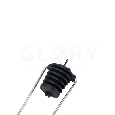


3 kN Aluminum Anchor Fiber Clamp
Glory Optical's aluminum anchor fiber clamp holds figure-8 and ordinary outdoor optical cables at pole-side anchor points in FTTH networks, with a 3–5 mm clamping-section range. It combines a die-cast aluminum shell and die-cast gripping teeth with SS201 stainless steel suspension wire and a hook-and-lock attachment. The clamp carries a 3 kN tension specification and an operating temperature range of −40°C to +80°C for outdoor fiber drops and branch routes.
 |
Aluminum Anchor Clamp3–5 mm clamping section 3 kN tension specification |
Aluminum Body and Gripping Details
 |
Gripping-Side ViewThe toothed gripping section and wire attachment shown in a complete assembly. |
 |
Shell-Side ViewRear view of the aluminum shell and upper attachment. |
 |
Die-Cast Gripping TeethClose-up of the metal teeth and the surrounding gripping-body structure. |
Anchor Structure and Material Features
Die-Cast Aluminum Shell
The shell uses die-cast aluminum around the gripping assembly. Its metal body holds the gripping components together at the anchor, giving the clamp a defined structure between the cable-contact section and the wire attachment.
Die-Cast Gripping Teeth
Metal teeth form the cable-contact area inside the assembly. The open gripping-side photograph shows their position along the central channel, allowing the contact layout to be reviewed with the selected cable profile.
SS201 Suspension Wire
SS201 stainless steel wire connects the gripping body to the upper attachment. Specifying the wire material alongside the aluminum body keeps the two structural materials identifiable when the hardware is scheduled for outdoor pole work.
3–5 mm Clamping Section
The clamping range covers a 3–5 mm section diameter. For figure-8 and other outdoor cable constructions, record the actual gripped section and profile so the cable-contact geometry follows the cable used at that anchor.
Hook-and-Lock Pole Attachment
The hook-and-lock structure connects the assembly to pole-side support hardware. Including the attachment geometry and cable approach in the mounting layout gives the installer a defined connection point for the selected anchoring position.
−40°C to +80°C Operation
The operating temperature range is −40°C to +80°C. Carrying this range into the site hardware schedule helps align the anchor selection with the intended outdoor environment and the cable specification for that route.
XS-B10S Technical Specifications
| Item | Specification |
|---|---|
| Product type | Aluminum anchor fiber clamp |
| Product line | Aerial Cable Anchoring & Pole Fittings |
| Tension specification | 3 kN |
| Clamping-section diameter | 3–5 mm |
| Cable constructions | Figure-8 optical cable and ordinary outdoor optical cable |
| Shell material | Die-cast aluminum |
| Gripping teeth material | Die-cast aluminum |
| Suspension wire material | 201 stainless steel |
| Attachment structure | Hook and lock |
| Mounting location | Fiber poles with compatible attachment hardware |
| Operating temperature | −40°C to +80°C |
FTTH and Outdoor Optical Cable Anchoring Applications
Figure-8 Optical Cable Anchor Points
At a pole anchor for figure-8 cable, the contact arrangement needs to follow the section actually held by the clamp. The XS-B10S provides a metal gripping channel inside its die-cast aluminum body, with a 3–5 mm clamping-section range. Its wire attachment connects that body to the pole-side hardware. Put the cable profile and gripped-section dimensions on the installation schedule, together with the support interface. This gives procurement a specific cable-to-clamp pairing and keeps the anchoring arrangement traceable when different figure-8 constructions are used across one access project.
Outdoor Fiber Distribution Cable Terminations
An outdoor cable arriving at a pole-mounted connection node needs a mechanical anchor before its continuation is organized toward the optical equipment. The XS-B10S combines its aluminum shell and gripping teeth at that anchoring point, while the SS201 wire provides the attachment to the support hardware. This arrangement keeps the cable-contact body and pole connection identifiable in the site layout. Select the gripped section within the 3–5 mm range, then include the cable construction, anchor position and project loading requirements when preparing the mounting package for that node.
FTTH Branch and Drop Routes
A pole carrying several FTTH branches may need different cable approaches and attachment positions for each outgoing route. Treating every drop as the same mounting arrangement can leave the bracket connection and cable profile unclear on the order. The hook-and-lock structure of the XS-B10S provides the pole-side connection for the selected anchor location. Pair it with the cable's gripped section and the required support hardware. Group project quantities by cable profile, pole interface and item reference, and include the −40°C to +80°C operating range in the equipment schedule.
Project Selection and Ordering
| Order item | Project information |
|---|---|
| Cable construction | Figure-8 or ordinary outdoor optical cable; identify the gripped section |
| Clamping section | Section diameter within 3–5 mm and the cable-contact profile |
| Material schedule | SS201 suspension wire with die-cast aluminum shell and teeth |
| Pole interface | Hook connection, compatible support hardware and cable approach |
| Project load requirement | Route loading requirements and the selected cable's anchoring requirements |
| Quantity and identification | Clamp quantity, item references, labels and packing arrangement |
Cable Anchoring Hardware · Outdoor Fiber Optic Cables
About Glory Optical
|
Glory Optical facility, Ningbo |
Glory OpticalFounded in 2008 · Ningbo, China · OEM/ODM support Ningbo Glory Optical Communication Co., Ltd. manufactures passive fiber optic products and supplies telecom operators, ISPs, contractors, distributors and OEM/ODM buyers. Our portfolio covers fiber boxes, splice closures, PLC splitters, fiber optic cables, patch cords, pigtails, adapters, MTP/MPO assemblies and installation accessories for fiber network projects. Manufacturing & OEM/ODM SupportManufacturing capabilities across our product families include mold development, enclosure molding, component assembly and fiber cable assembly. OEM/ODM projects can cover drawings, product configuration, samples, branding, labels and packaging, according to the selected product and confirmed requirements. |

Testing Capabilities
Glory Optical supports inspection and testing according to confirmed product specifications and order requirements. The following videos show examples from our testing activities.
Water Spray Testing |
Sealing Performance Testing |
Water Resistance Testing |
Project Supply & OEM Support
For XS-B10S orders, send the cable profile, clamped-section diameter, pole attachment and quantity. Glory Optical can discuss the selected hardware, samples, item labels and project packing arrangements.
Discuss Your Product or Project Requirement
Send the product model, quantity, application and required configuration for quotation or sample discussion. Include any drawing, labeling, packaging and documentation requirements so our team can review the order details.
Email: sales@gloryoptic.com
Hot Tags: aluminum anchor fiber clamp, China aluminum anchor fiber clamp manufacturers, suppliers, factory, fiber optic cable termination kit, fiber tool box, fo cable splicing kit, ftth tool kit, optical fiber tool kit, tool kit fiber optic