

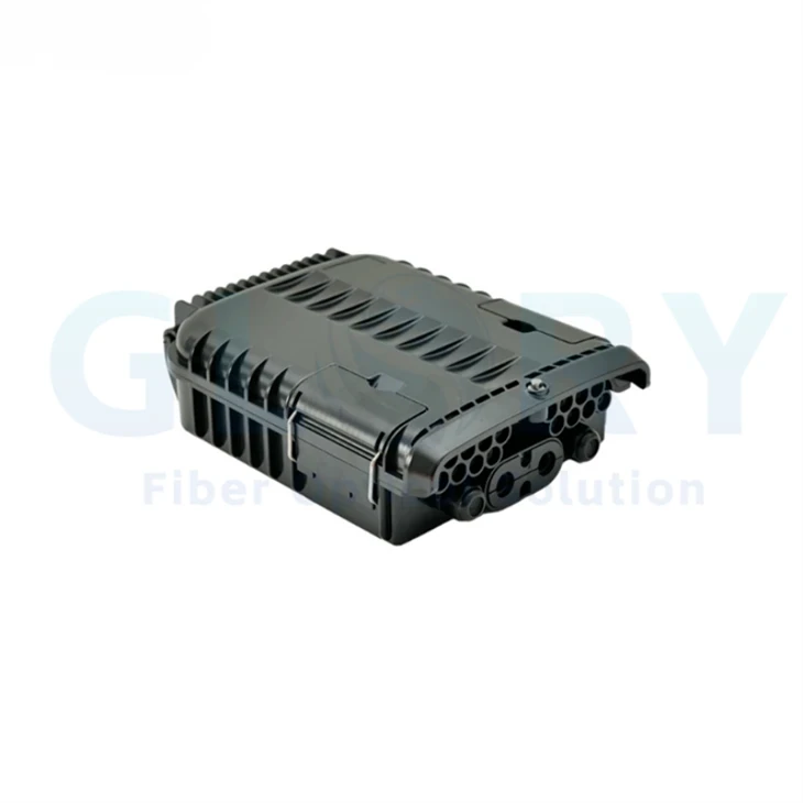


GL-A1-16R Fiber Optic Terminal Closure
The GL-A1-16R is a 16-port fiber optic terminal closure for feeder-to-drop termination and distribution in FTTx networks. Its 290 × 210 × 82 mm PC/ABS housing is listed for IP66 protection, with SC/APC or SC/UPC connector configurations and an operating range of −40°C to +85°C. Wall and pole arrangements support building-entry, MDU and campus access points; confirm the adapter population, internal fiber layout and cable-entry sealing parts for the selected assembly.
|
|
16-Port FTTx Termination and DistributionModel: GL-A1-16R Listed size: 290 × 210 × 82 mm Connector options: SC/APC or SC/UPC · Protection: IP66 Select the internal loading and matched feeder/drop cables for the order. Confirm the supplied finish and mounting kit in the assembly drawing. |

Technical Specifications
|
Parameter |
Specification / configuration |
|---|---|
|
Connector ports / polish options |
16 ports, SC/APC or SC/UPC connectors |
|
Insertion Loss |
≤ 0.2 dB (typical), ≤ 0.3 dB (maximum) |
|
Return Loss |
≥ 55 dB (APC), ≥ 50 dB (UPC) |
|
Operating Temperature |
-40°C to +85°C |
|
Protection Rating |
IP66 (dust-tight and protected against powerful water jets) |
|
Material Construction |
High-impact PC+ABS composite with UV stabilization |
Optical acceptance: Confirm the interface, test wavelength and measurement reference for the stated insertion-loss and return-loss figures. These figures do not define the total loss of an unspecified internal splitter or a complete subscriber link.
Wall and Pole Configuration
|
Parameter |
Wall mounting |
Pole mounting installation |
|---|---|---|
|
Listed capacity (fibers) |
16 core |
16 core |
|
Size(mm) |
290*210*82 |
290*210*82 |
|
Material |
PC/ABS |
PC/ABS |
|
Color |
black |
black |
The 16-core entries describe the listed configuration capacity; the 16-port specification describes connector positions. Confirm the actual adapters, splices, pigtails and any splitter separately. Rack mounting is mentioned in the installation description and requires its model-specific bracket and clearance confirmation.
GL-A1-16R Structure and Cable Management
Feeder-to-Drop Fiber Organization
The enclosure provides a managed transition from feeder cable to the selected drop-cable connections. Define the incoming fiber allocation, splice arrangement and numbered adapter schedule before assembly. Use the 16-position connector requirement together with the approved internal map.
PC/ABS Housing with IP66 Protection
The material is described as high-impact PC+ABS with UV stabilization, and the listed wall and pole configurations use PC/ABS. Confirm the cable seals, closure arrangement and required assembled IP66 test conditions for the actual installation.
SC/APC or SC/UPC Configurations
Specify the required SC polish and matched pigtail and patch-cord assemblies throughout each connection. The published optical entries distinguish APC and UPC return loss. Keep connector preparation and test conditions with the selected interface specification.
Internal Routing and Cable Retention
Organize feeder retention, fiber slack and splice protection around the supplied tray and adapter arrangement. Confirm the minimum bend limits of the actual fibers and cables and the mechanical retention parts fitted to the order. No numerical bend-radius or cable-retention load is specified.
Wall and Pole Mounting Options
Both listed installation configurations use a 290 × 210 × 82 mm housing and black color. Select the bracket, fixing parts and cable approach for the site. Check opening access, plug clearance and cable support before approving the mounting drawing.
|
|
Open Enclosure and Internal ArrangementThe original open-unit photograph shows the internal fiber-management area and adapter panel. Match the supplied tray, pigtail and cable-entry arrangement to the approved GL-A1-16R assembly. Specify any required optical splitter and its ratio in the bill of materials. The enclosure photograph alone does not establish a splitter circuit or splice capacity. |

FTTH and FTTx Application Planning
MDU and Building-Entry Fiber Distribution
At a multi-dwelling building, the feeder cable and subscriber drops need an organized termination point with a clear connection schedule. Install the selected GL-A1-16R wall or pole arrangement at the approved building-entry or access location. The 16 SC connector positions support the specified pigtail and drop configuration, while the internal layout must follow the building fiber plan. Before ordering, confirm cable construction, entry sealing, splice allocation, adapter polish, labels and any required splitter. Check the assembled protection conditions and the space needed to open and service the enclosure.
Campus and Business-Park Access Nodes
A campus or business park may distribute feeder fibers to several buildings, creating different requirements for route allocation and drop lengths. Use the GL-A1-16R as the planned termination node between the distribution cable and matched drop connections. Select the internal circuit for the project topology and confirm where any PON splitting or WDM components are located. Before procurement, approve the wall or pole mounting kit, cable sizes, connector schedule and fiber routing. Include the intended service-access procedure and optical inspection requirements with the assembly drawing and site installation plan.
Outdoor Cabinets and Distributed Fiber Links
An outdoor cabinet or distributed communications site needs the enclosure and cable arrangement matched to its installed position. The GL-A1-16R provides the listed PC/ABS housing and wall or pole configuration for the planned fiber termination point. Confirm the mechanical space, cable approach and SC/APC or SC/UPC connections before selecting the assembly. For a proposed mobile, DAS or equipment-side link, have the system design define fiber allocation, receiving interfaces and optical-path requirements. Request project-specific evidence for the relevant conditions rather than treating an application illustration as a product qualification.
Network and Installation Context Illustrations
These illustrations provide planning context for passive fiber termination. Confirm the actual network components, interfaces and enclosure location for the project; the illustrations do not define the internal optical circuit of this model.
|
|
Equipment-Side Optical ConnectionsFor equipment-side or mobile-network fiber links, identify the receiving port, cable assembly and required fiber map. Confirm whether this enclosure serves as a splice, termination or distribution point in the approved design. |

|
|
FTTH Passive Optical Network PlanningPlan the terminal location relative to the feeder, distribution fibers and subscriber drops. The network drawing includes separate optical components; specify their location and any splitter loading required in the enclosure. |

|
|
Equipment-Room Interconnection PlanningFor a proposed equipment-room interconnection, confirm the passive termination role, connector interface and cable route. Transmission equipment, reach and bandwidth depend on the complete system design. |

|
|
Industrial Fiber-Link PlanningFor an industrial site, confirm the fiber route and actual environmental and mounting conditions. This general illustration is not a GL-A1-16R installation case or evidence of qualification for a particular industrial environment. |

Installation, Inspection and Project Documentation
|
Parameter |
Specification / configuration |
|---|---|
|
Primary listed mounting arrangements |
Wall mounting and pole mounting |
|
Other arrangement mentioned |
Rack mounting; confirm the specific bracket, attachment and clearance |
|
Cable-entry diameter range stated |
4–16 mm; confirm the selected cable profile, entry position and sealing kit |
|
Fiber and cable management |
Approved retention parts, minimum bend limits, fiber identification and adapter schedule |
|
Inspection and service access |
Confirm the installed cover / panel arrangement, connector access and agreed inspection procedure |
The supplied description names Telcordia GR-487 and IEC 61753 without identifying a test report, edition or performance category. Confirm the applicable project criteria and supporting documents for the ordered assembly. Any ITU-T requirement should be identified by its specific recommendation and scope.
Define the required optical acceptance and service-access procedure in the project documents. If monitoring or in-service testing is required, identify the optical access arrangement and method in the approved circuit.
Selection and Ordering Details
|
Confirm before ordering |
Required project details |
|---|---|
|
Model and loading |
GL-A1-16R; adapter population, fiber allocation, splice layout and any separately specified splitter |
|
Connector interfaces |
SC/APC or SC/UPC, matched pigtails / patch cords, test reference and optical acceptance limits |
|
Cable entry |
Feeder and drop cable constructions, diameters, entry positions and selected sealing parts |
|
Mechanical installation |
Wall or pole kit, listed 290 × 210 × 82 mm housing, access space and cable support |
|
Environment and documents |
IP66 assembled conditions, −40°C to +85°C operation and applicable inspection / test documents |
|
Identification and supply |
Quantity, drawing / sample approval, port labels, packaging and required project records |
Send Glory Optical the required port schedule, feeder/drop cable details, connector polish and installation drawing for configuration review. Include any special mounting, component loading, labeling and inspection requirements with the quotation request.
Related Product Category
About Glory Optical
|
Glory Optical facility, Ningbo |
Glory OpticalFounded in 2008 · Ningbo, China · OEM/ODM support Ningbo Glory Optical Communication Co., Ltd. manufactures passive fiber optic products and supplies telecom operators, ISPs, contractors, distributors and OEM/ODM buyers. Our portfolio covers fiber boxes, splice closures, PLC splitters, fiber optic cables, patch cords, pigtails, adapters, MTP/MPO assemblies and installation accessories for fiber network projects. Manufacturing & OEM/ODM SupportManufacturing capabilities across our product families include mold development, enclosure molding, component assembly and fiber cable assembly. OEM/ODM projects can cover drawings, product configuration, samples, branding, labels and packaging, according to the selected product and confirmed requirements. |

Testing Capabilities
Glory Optical supports inspection and testing according to confirmed product specifications and order requirements. The following videos show examples from our testing activities.
Water Spray Testing |
Sealing Performance Testing |
Water Resistance Testing |
Specification Review & Project Documentation
Before batch production, confirm the drawing or sample, product configuration, inspection requirements and packing details. For connectorized products, applicable inspection can include insertion loss, return loss and connector end-face checks. Datasheets, drawings and applicable test documents can be discussed for the order.
Discuss Your Product or Project Requirement
Send the product model, quantity, application and required configuration for quotation or sample discussion. Include any drawing, labeling, packaging and documentation requirements so our team can review the order details.
Email: sales@gloryoptic.com
Hot Tags: fiber distribution box outdoor, China fiber distribution box outdoor manufacturers, suppliers, factory, box fiber, fiber closure box, Fiber Optic Box Wall, Fiber Optic Cable Junction Box, Fiber Termination Enclosure, Nid Box


