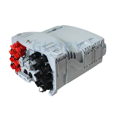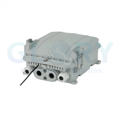
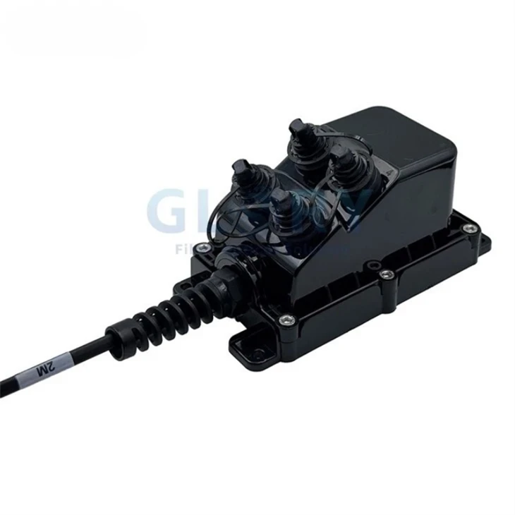


GL-MST02-04 4-Port Fiber Optic Multiport Service Terminal Box
The GL-MST02-04 is a four-port outdoor Multiport Service Terminal (MST) for pre-connectorized FTTH distribution and fiber indexing projects. The specified SC/APC hardened interface is paired with a stubbed cable configuration, with toneable or dielectric cable options and a stated IP67 rating. Typical insertion loss is listed at ≤0.15 dB and typical reflectance at −65 dB; select the cable length, connector arrangement and mounting kit for the planned access node.
|
|
Four-Port MST with Stub Cable ConfigurationModel: GL-MST02-04 Interface: SC/APC hardened adapter; confirm the exact H-connector pairing. Protection: IP67 · Stub lengths: 20–1000 ft listed, with other lengths available. Assembly photograph supplied with the product information. Confirm the feeder end, internal circuit and connector parts against the ordered assembly drawing. |

Product Family: Outdoor Multiport Service Terminals
The GL-MST02-04 is the four-port model presented for fiber indexing and pre-connectorized access deployments. The broader family lists 2, 4, 6, 8 and 12-port configurations. Specify the required model and the numbered port-to-fiber map for each project.
MPO pigtails are named in the cable-assembly specification. Confirm the multifiber feed, local drop allocation and any downstream indexing path in the circuit drawing; these functions depend on the selected assembly.
GL-MST02-04 MST Features
Four-Port Configuration Within a Multiport Family
Select GL-MST02-04 for the four-port requirement. The family table lists 2, 4, 6, 8 and 12 ports, so the housing, connector schedule and cable map should be tied to the exact model on the purchase order. Distinguish the number of connection positions from the number of fibers carried by a multifiber input.
SC/APC Hardened Drop Connections
The specified adapter is SC/APC hardened and described for H-connector mating. Confirm the complete plug, receptacle, keying, lock and seal combination. The separately listed ODVA, OptiTap, Mini SC, ODC, PTLC and PTMPO families require their own approved variants and matching cable assemblies.
Toneable or Dielectric Stub Cable Options
Cable options include toneable or dielectric constructions in the listed 4.5 × 9.8, 4.5 × 8.1 and 4.0 × 7.0 mm profiles. Stub lengths range from the listed 20 ft through 1000 ft, with other lengths available. Match the construction, cable ends and lead length to the route and termination plan.
Typical Optical Performance Values
Typical insertion loss is listed as ≤0.15 dB and typical reflectance as −65 dB. Keep these quantities and their signs with the interface specification. Confirm the test wavelengths, measurement reference and production acceptance limits for the complete ordered assembly.
Outdoor Housing and Installation Options
The product description states IP67 and lists pole, pedestal, handhole and strand mounting, with wall and aerial arrangements also described. Connector angles and heights are arranged to reduce interference during access. Confirm the mounting kit, connected-plug clearance, sealing conditions and cable routing for the site.
Technical Specifications
|
Parameter |
Specification / configuration |
|---|---|
|
Product Name |
Multiport Service Fiber Optic Terminal - Single-tube Gel-Filled Cable, Toneable, Stubbed with MPO pigtails |
|
Cable Type |
Toneable or Dielectric Cables |
|
Cable Diameter |
4.5*9.8mm 4.5*8.1mm 4.0*7.0mm |
|
Installation |
Pole, pedestal, handhole or strand mounting options |
|
Stub Length |
20ft,40ft,50ft,60ft,80ft,100ft,150ft,200ft,250ft,300ft,500ft,800ft,1000ft(Other lengths are available) |
|
Insertion loss, Typical |
≤0.15dB |
|
Reflectance, Typical |
-65dB |
|
Adapter Type |
SC/APC Hardened adapter, Compatible with H connector |
|
Fiber Ports |
2,4,6,8,12 |
The Fiber Ports row describes the product family; this page presents GL-MST02-04 as the four-port model. The typical loss and reflectance entries require the agreed test reference and do not define the loss of an unspecified internal splitter.
Housing and Configuration Options
|
Parameter |
Specification / configuration |
|---|---|
|
Model presented |
GL-MST02-04 |
|
Selected model port count |
4 ports |
|
Protection rating |
IP67 |
|
Assembly options |
Factory-sealed configuration or field assembly, according to the selected design |
|
Internal optical configuration |
Optional PLC splitter or splice-sleeve arrangement; confirm the circuit and components |
|
Long-term pulling force, stated |
Up to 1200 N; confirm the applicable cable / assembly and test conditions |
|
Additional interface families for review |
ODVA, OptiTap, Mini SC, ODC, PTLC and PTMPO; select the specific variant |
|
Power-adapter configuration |
Requires a separate approved interface and electrical specification if requested |
|
Performance reference |
IEC 61753-1; confirm the applicable performance category, tests and supporting documents |
A PLC splitter divides optical power. A splice sleeve protects a fiber joint and does not itself perform optical splitting. Specify the intended internal function and any required split ratio in the circuit drawing.
Housing Reference Drawing
|
|
Confirm the Selected Housing VariantThe original drawing includes two housing layouts and dimensional annotations. Match the appropriate layout to the four-port GL-MST02-04 order. Confirm drawing units, tolerances, mounting points and clearance with mating plugs installed. Use the approved assembly drawing for installation planning. |

FTTP Network Position
|
|
Distribution Cable to Subscriber DropsThe illustration places MST nodes at pedestal, handhole and aerial access points between the fiber distribution network and subscriber drop cables. Confirm the feeder, local drop map and upstream split location. Any indexing or downstream continuation path must follow the project circuit drawing. This is a general FTTP network illustration; it does not define the internal fiber map of the GL-MST02-04. |

FTTH and Fiber Indexing Application Planning
Fiber Indexing Access Routes
A fiber indexing route requires a defined relationship between the incoming multifiber cable, local subscriber connections and any continuing fibers. The GL-MST02-04 is presented for this deployment approach, with a stubbed cable description that names MPO pigtails. Position the selected terminal at the planned access node and approve the complete fiber map before ordering. Confirm input and output connector parts, local drop assignments, any downstream continuation, fiber count and polarity. The four-port designation alone does not establish an indexing sequence or the capacity of a continuing multifiber path.
FTTH Distribution-to-Drop Connections
At a neighborhood access point, the terminal must connect the distribution route to the correct subscriber drops while preserving the intended optical circuit. Select the four-port SC/APC hardened configuration for matched drop assemblies and place it at the planned pole, pedestal or handhole node. Confirm where splitting takes place in the network and whether the ordered terminal requires a PLC module or a splice arrangement. Before procurement, approve the connector pairing, stub length, numbered port map and complete path-loss budget. Include sealing instructions and unused-port treatment with the installation documents.
Outdoor Route and Stub Cable Planning
A fixed cable length or unsuitable cable construction can leave excess slack or prevent the terminal from reaching its intended connection point. Toneable or dielectric options and the listed stub-length choices support a route-specific assembly plan. Install the selected MST with the approved pole, pedestal, handhole or strand kit, allowing space for plugs and cable routing. Before ordering, confirm the flat cable profile, required stub length, attachment method, bend limits and sealing conditions. Have the supplier identify the cable or assembly covered by the stated 1200 N long-term pulling figure.
Selection and Ordering Details
|
Confirm before ordering |
Required project details |
|---|---|
|
Model and port count |
GL-MST02-04, four-port configuration; approved housing variant |
|
Optical function |
Indexing / distribution circuit, local drops, downstream mapping and any PLC ratio |
|
Input and output interfaces |
SC/APC hardened drop parts, MPO pigtail details, keying, polarity and matching cable assemblies |
|
Cable and stub |
Toneable or dielectric construction, cable profile, exact length and both end terminations |
|
Optical acceptance |
Typical values versus agreed acceptance limits, test wavelengths and measurement reference |
|
Mechanical and environmental checks |
Applicable 1200 N test, IP67 assembled conditions, mounting kit and plug clearance |
|
Performance documents |
IEC 61753-1 category and requested test records; no certification status inferred |
|
Project supply |
Quantity, sample and drawing approval, labels, packaging and inspection documents |
Send Glory Optical the GL-MST02-04 model requirement, fiber map, mating connector parts, stub length and installation location for configuration review. Include any field-assembly or factory-sealing requirement with the order.
About Glory Optical
|
Glory Optical facility, Ningbo |
Glory OpticalFounded in 2008 · Ningbo, China · OEM/ODM support Ningbo Glory Optical Communication Co., Ltd. manufactures passive fiber optic products and supplies telecom operators, ISPs, contractors, distributors and OEM/ODM buyers. Our portfolio covers fiber boxes, splice closures, PLC splitters, fiber optic cables, patch cords, pigtails, adapters, MTP/MPO assemblies and installation accessories for fiber network projects. Manufacturing & OEM/ODM SupportManufacturing capabilities across our product families include mold development, enclosure molding, component assembly and fiber cable assembly. OEM/ODM projects can cover drawings, product configuration, samples, branding, labels and packaging, according to the selected product and confirmed requirements. |

Testing Capabilities
Glory Optical supports inspection and testing according to confirmed product specifications and order requirements. The following videos show examples from our testing activities.
Water Spray Testing |
Sealing Performance Testing |
Water Resistance Testing |
Specification Review & Project Documentation
Before batch production, confirm the drawing or sample, product configuration, inspection requirements and packing details. For connectorized products, applicable inspection can include insertion loss, return loss and connector end-face checks. Datasheets, drawings and applicable test documents can be discussed for the order.
Discuss Your Product or Project Requirement
Send the product model, quantity, application and required configuration for quotation or sample discussion. Include any drawing, labeling, packaging and documentation requirements so our team can review the order details.
Email: sales@gloryoptic.com
Hot Tags: fiber optic terminal, China fiber optic terminal manufacturers, suppliers, factory, fiber breakout box, fiber connection box, fiber termination box, fiber wall box, outdoor fiber junction box, terminal box fiber