
The Invisible Backbone of Every Fiber Network
Every fiber-to-the-home deployment has a weak link, and it is rarely the laser or the fiber itself. It is the point where two cables meet - the splice - and the humble box that keeps it alive for decades outdoors. When telecom operators plan a fiber-to-the-home network, the conversation tends to orbit around the glamorous end of the chain: the OLT in the central office pushing 2.5 gigabits per second downstream, the splitter dividing one feeder into thirty-two drop fibers, the ONT blinking green on a living-room shelf. All of that works only if the physical layer connecting those endpoints survives twenty or thirty years of weather, vibration, and neglect.
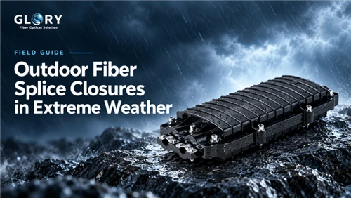
The component carrying that burden - quietly, without a single LED to indicate it is doing its job - is the splice closure. A splice closure is, at its simplest, a sealed enclosure that houses the fusion-splice joints between two lengths of optical fiber cable. In an FTTH context, these joints appear at every point where the network branches, transitions between cable types, or shifts between deployment media: aerial to underground, underground to riser, riser to indoor. A moderately sized FTTH project serving a neighborhood of 500 homes might deploy 40 to 80 splice closures along its route. Get any of them wrong, and you have created a failure point that will cost a technician a truck roll, a splice rig, and two hours of field time to diagnose and repair - not to mention the SLA penalty while subscribers sit in the dark.

PON Technology Context: Why Fiber Architecture Matters
Before examining the splice closure itself, it helps to understand the network architecture it serves. FTTH networks are built on Passive Optical Network (PON) technology, which uses unpowered optical splitters to distribute a single fiber from the central office to multiple subscribers. The two dominant PON standards are GPON (Gigabit PON, defined by ITU-T G.984) and EPON (Ethernet PON, defined by IEEE 802.3ah). GPON operates at 2.488 Gbps downstream and 1.244 Gbps upstream, using wavelengths of 1490 nm and 1310 nm respectively. It supports a split ratio of up to 1:64 and a maximum reach of 20 kilometers from the OLT. EPON offers 1.25 Gbps symmetric bandwidth with typical split ratios of 1:32 or 1:64.
The splitter is where the physics gets interesting. A 1x32 PLC splitter divides the incoming optical signal into 32 equal outputs, but each division costs signal power. The insertion loss grows logarithmically with the split count: a 1x2 splitter introduces roughly 3.5 dB of loss, a 1x8 about 10.7 dB, a 1x32 about 17.5 dB, and a 1x64 about 21.5 dB. Against this, the GPON optical budget for Class B+ is 28 dB, and Class C+ extends to 32 dB. That budget must absorb splitter loss, fiber attenuation (roughly 0.35 dB/km at 1310 nm and 0.22 dB/km at 1490 nm), connector losses (0.3 to 0.5 dB per mated pair), and - critically for this discussion - splice losses.
A well-executed fusion splice introduces 0.05 dB or less of loss. A poorly executed one can add 0.3 dB or more. In a network with 80 splice closures, each containing multiple splices, the cumulative splice loss can mean the difference between a link that passes the optical budget and one that falls short. This is why the splice closure is not merely a protective enclosure - it is a signal-integrity component whose design and installation directly affect whether the network can deliver the promised bandwidth to the subscriber at the end of the line.
|
Split Ratio |
Max Insertion Loss (dB) |
Typical Deployment |
Homes Served |
|
1x4 |
7.4 |
Small MDU, rural |
4 |
|
1x8 |
10.7 |
Mid-density residential |
8 |
|
1x16 |
13.8 |
Urban FTTH |
16 |
|
1x32 |
17.5 |
High-density GPON |
32 |
|
1x64 |
21.5 |
Max density, short reach |
64 |
Where Splice Closures Fit in the FTTH Chain
An FTTH network is best understood as a series of layers, each with its own cable type, splice density, and deployment environment. The feeder layer runs from the central office to a primary distribution point, typically using G.652D loose-tube cable with 48 to 96 fibers. At the distribution point, a 1x32 or 1x64 PLC splitter fans the signal out toward neighborhoods, and the cable transitions to a smaller distribution cable carrying 12 to 48 fibers. The drop layer then runs G.657A2 bend-insensitive fiber from a street cabinet or pole-mounted access point to each subscriber's home, terminating at an indoor wall box or ONT.
Splice closures sit at the junctions between these layers. On the feeder side, they aggregate multiple cables entering from different directions and splice them into the distribution cable heading toward splitters. On the distribution side, smaller closures at poles or handholes handle the fan-out to individual drops. The closure is doing two jobs simultaneously: protecting the fused glass joint from the environment, and providing a managed space where excess fiber can be coiled, rerouted, and accessed for future maintenance.
|
Network Layer |
Cable Type |
Splices per Closure |
Deployment Location |
|
Feeder |
G.652D, 48-96F |
48-96 |
Aerial pole / manhole |
|
Distribution |
G.652D / G.657A2, 12-48F |
12-48 |
Pole / handhole / cabinet |
|
Drop |
G.657A2, 1-4F |
4-12 |
Building entry / wall box |
The Fragility Problem: Why Splices Need Protection
A fusion splice is a remarkable piece of engineering. An arc of electricity melts two glass cores at roughly 2,000 degrees Celsius, fusing them into a continuous path for light with insertion loss often below 0.05 dB. The splice joint itself is strong - nearly as strong as the uncut fiber. But the 30 to 50 millimeters of bare fiber surrounding the splice, stripped of its coating for the fusion process, is astonishingly fragile. A bend tighter than 10 mm radius on standard G.652 fiber, or 5 mm on G.657 bend-insensitive fiber, will introduce micro-bending loss that degrades the signal or shatters the glass entirely.
This is the engineering problem the splice closure solves. Inside the closure, a splice tray holds each fusion splice in a protected groove, and the excess fiber is coiled into a loop with a minimum radius enforced by the tray geometry - typically 30 to 60 mm, well above the critical bend threshold. The tray is then stacked inside the sealed closure body, where it is shielded from everything the outside world throws at it: rain, condensation, UV radiation, temperature swings from minus 40 to plus 65 degrees Celsius, wind-borne dust, and rodents.
Water is the single most common cause of ODN field failure. When moisture penetrates a splice closure, it causes hydrogen loss in the optical fiber and corrodes any metal reinforcement in the cable. A closure that holds IP68 under laboratory conditions but fails after three freeze-thaw cycles in a Minnesota February is not a closure - it is a liability.
Splice Closure Anatomy: Inside the Box
A modern splice closure is more than a plastic shell. It is a precision-engineered assembly of interacting components, each serving a specific function in the protection and management chain. Understanding these components clarifies why seemingly minor design differences between manufacturers translate to large differences in field performance.
The Closure Body
The outer shell is the first line of defense, typically injection-molded from ABS, reinforced polycarbonate, or glass-filled polypropylene. The material choice balances UV resistance, impact strength across the operating temperature range, and dimensional stability. Dome-type bodies are cylindrical with a domed end cap, designed so that water and debris shed naturally off the curved surface. Horizontal or inline bodies are rectangular, optimized for tight spaces like handholes and building entry points. The body wall thickness ranges from 3 to 6 mm, with internal ribs for structural stiffness.
Splice Trays
Trays are the organizational heart of the closure. Each tray holds a defined number of fusion splices - typically 12 to 24 - in molded V-grooves that hold the splice protection sleeves in place. The tray also provides a routing path for the excess fiber, with a minimum bend radius molded into the plastic geometry. Trays are modular and stackable, connected by a central hinge or post that allows each tray to be lifted independently for splice access without disturbing adjacent trays. This stack-and-lift design is what makes it possible to service one splice without risking micro-bending damage to dozens of others.
Cable Entry and Sealing System
Cables enter the closure through ports in the body, typically at one or both ends. Each port must form a watertight seal around the cable jacket while also providing strain relief. The sealing system - mechanical grommets, heat-shrink sleeves, or a combination - is the component most likely to fail over time. Port designs often include a tapered entry that compresses the sealing element as the cable is inserted, and a secondary clamp that provides mechanical retention independent of the seal.
Grounding and Bonding Hardware
Metallic cable armor and central strength members must be grounded to protect against lightning strikes and electrical faults. The closure includes grounding hardware - typically brass or stainless steel clamps and a grounding stud - that bonds the cable's metallic elements to a common point. This is not optional: an ungrounded closure with metallic armor can accumulate charge differentials that arc across fiber, causing progressive damage that manifests as intermittent signal loss long before anyone suspects the closure.
Sealing: Mechanical vs Heat-Shrink

The sealing mechanism is where the real engineering trade-off lives. Two approaches dominate the market, and choosing between them should depend on how the closure will be used over its lifetime, not on the sticker price.
Mechanical seals use rubber grommets, O-rings, and clamp systems to create a watertight barrier around each cable port and at the closure's main seam. Their advantage is reversibility: a technician can open the closure, add a new cable, re-splice, and reseal without replacing any consumable parts. For closures at distribution points where subscriber count grows over time, this matters enormously. The disadvantage is that the seal depends on the gasket's compression, which degrades over years of thermal cycling. A mechanical seal rated IP68 on day one may allow slow water ingress after five winters if the gasket material hardens.
Heat-shrink seals use heat-melt adhesive tubes that bond permanently to the cable jacket and closure body. Once shrunk, the seal is essentially airtight and highly resistant to vibration and mechanical pull. The trade-off is irreversibility: opening a heat-shrink closure means cutting the sleeve off and replacing it with a new one. For backbone or feeder splice points that should never need re-entry, this is ideal. For distribution points where you expect to add fibers as new homes come online, it is a mistake.
The IP rating tells you how well the seal performs under specific test conditions. IP67 means the closure withstands temporary submersion at 0.15 to 1 meter depth. IP68 means continuous immersion at a depth and duration defined by the manufacturer, which is the floor for any closure placed in a manhole, handhole, or direct-buried application. But here is the subtlety: IEC 60529, the standard that defines these ratings, leaves the exact depth and duration of IP68 testing to the manufacturer's declaration. Two closures both labeled IP68 may have been tested at 1 meter for 24 hours and 2 meters for 7 days, respectively. Specifying IP68 is a starting point, not an endpoint - responsible procurement demands the actual test parameters.
|
Factor |
Mechanical Seal |
Heat-Shrink Seal |
Recommendation |
|
Reusability |
Yes, no consumables |
No, sleeve replaced |
Mechanical for growth |
|
Seal longevity |
5-10 years, degrades |
15+ years, stable |
Heat-shrink for backbone |
|
Vibration resistance |
Moderate |
Excellent |
Heat-shrink near roads |
|
Installation time |
Faster, no torch |
Slower, requires torch |
Mechanical for speed |
|
Typical IP rating |
IP67-IP68 |
IP68+ |
Verify test parameters |
Dome vs Horizontal: Choosing the Right Form Factor
The choice between dome and horizontal closures is not aesthetic. It is a deployment-driven decision based on mounting location, fiber count, access patterns, and environmental exposure. Both form factors can meet IP68 requirements and house the same internal components, but their physical geometry makes each better suited to specific scenarios.
Dome closures are cylindrical with a domed end cap, sealing via a clamp and O-ring system at the base. Cables enter from the bottom in a single-end configuration. This orientation means water and debris naturally shed off the curved surface, making dome closures the default choice for aerial and pole-mounted deployments where the closure is exposed to direct rainfall. Their vertical profile also means they sit compactly against a pole, minimizing wind load. Typical capacities range from 12 to 288 cores, with trays stacking vertically inside the dome.
Horizontal or inline closures are rectangular, with cables entering through ports on one or both ends. They seal via a hinged lid with a peripheral gasket or via mechanical clamps. Their low profile suits tight spaces: handholes, pedestals, building entry points, and within distribution cabinets. Horizontal closures tend to offer easier tray access because the lid opens from the top, giving the technician a full view of all trays simultaneously. Typical capacities range from 12 to 144 cores.
|
Criterion |
Dome |
Horizontal / Inline |
Notes |
|
Best mounting |
Aerial, pole, manhole |
Handhole, pedestal, cabinet |
Match to physical space |
|
Water shedding |
Excellent (curved surface) |
Good (gasket-dependent) |
Dome wins outdoors |
|
Tray access |
Sequential, bottom-up |
Simultaneous, top-open |
Horizontal for maintenance |
|
Max capacity |
288+ cores |
144 cores typical |
Dome for high density |
|
Wind load |
Low (aerodynamic) |
Moderate (flat surface) |
Dome for aerial |
Cable Management as Engineering, Not Housekeeping
There is a tendency to think of cable management inside a closure as aesthetics - keeping things tidy so the next technician does not curse your name. In reality, it is a reliability decision with quantifiable consequences.
Consider what happens when a technician opens a closure to troubleshoot a single failed splice. If the fibers inside are arranged haphazardly - coiled at inconsistent radii, crossing over each other, bundled with zip ties - the act of lifting one tray to reach a deeper one can introduce micro-bends in adjacent fibers. The technician came to fix one subscriber's connection and has now degraded three others. This is not hypothetical; it is one of the most common causes of no-fault-found service calls, where the technician closes the closure, the connection tests fine, and the subscriber's intermittent loss returns a week later when vibration settles the fibers back into their damaged configuration.
A well-designed splice tray solves this by enforcing geometry. Each splice sits in a V-groove that holds it in place. Excess fiber follows a defined path with a guaranteed minimum bend radius. Trays stack vertically with enough clearance that one can be lifted without disturbing the others. The closure body includes cable routing guides that separate incoming feeder cables from outgoing drop cables, preventing crosstalk-level micro-bending at the entry ports.
The practical implication for network planners: when evaluating closures, look at the tray-to-fiber ratio. A closure advertising 144-core capacity with only four trays means each tray holds 36 splices - a density that makes individual splice access difficult without disturbing neighbors. Eight trays of 18 splices each costs more but dramatically reduces the risk of collateral damage during maintenance. The cost difference is marginal; the reliability difference is substantial.
Installation Best Practices: What the Field Demands
The quality of a splice closure deployment depends as much on installation discipline as on product selection. The best closure on the market will fail prematurely if the installer skips steps, over-torques bolts, or stores fiber at the wrong bend radius. The installation sequence breaks into five phases.
Pre-Installation: Site and Cable Preparation
Before opening the closure, the installer must verify the cable type, fiber count, and route against the engineering design. For aerial closures, the pole location and mounting height must allow safe ladder or bucket-truck access. For underground closures, the handhole must be clean, dry, and large enough for the closure body and cable bending radius. The cable itself is prepared by removing the outer jacket to the specified stripping length, exposing the strength member and fiber buffer tubes. This is where many problems begin: over-stripping exposes too much bare fiber, while under-stripping prevents proper sealing at the cable port.
Fiber Splicing
Each fiber is stripped of its 250-micron coating using a mechanical stripper, cleaved to a precise end-face angle using a precision cleaver, and placed into the fusion splicer. The splicer aligns the fiber cores, initiates the arc, and verifies the splice quality through loss estimation and tension testing. A splice protection sleeve is then positioned over the bare fiber section and heat-shrunk to provide mechanical protection. The protected splice is placed into the tray's V-groove, and excess fiber is routed along the tray's coil path with attention to minimum bend radius. Splice losses should be verified to be below 0.1 dB; any splice exceeding 0.3 dB should be re-done.
Tray Loading and Cable Routing
Splices are loaded into trays in sequence, starting from the lowest tray and working upward. Each tray should be filled to its design capacity before moving to the next, rather than spreading splices across multiple partially filled trays. Excess fiber slack - typically 1 to 2 meters per splice - must be stored in the tray's coil path, not left loose inside the closure body. The closure body's internal routing guides separate incoming feeder cables from outgoing drop cables, and any unused cable ports must be sealed with blanking plugs to maintain the environmental seal.
Sealing and Closure
For mechanical seals, the installer compresses each cable port grommet to the manufacturer's specified torque - over-tightening can deform gaskets and create leak paths, while under-tightening allows water ingress. For heat-shrink seals, the installer applies a propane torch evenly around the sleeve, watching for adhesive flow at both ends to confirm a complete seal. After sealing, the closure lid is closed and secured, and the entire assembly is mounted to its bracket, pole, or handhole fixture with appropriate hardware.
Post-Installation Testing
Before the crew leaves the site, the installer must verify the optical path. An OTDR (Optical Time-Domain Reflectometer) trace confirms that each splice is within loss tolerance and that no macro-bends were introduced during tray loading. The trace also serves as a baseline for future maintenance - a subsequent trace that shows new reflective or non-reflective events at a splice point immediately localizes the fault. Any closure that has been opened for maintenance should be re-tested before it is sealed and left unattended.
Scalability Without Re-Digging
FTTH networks are built in phases. A developer breaks ground on a new subdivision, and the operator lays feeder cable with 96 fibers, expecting to light up 32 homes immediately and another 64 within five years. The splice closure at the distribution point must accommodate that growth without requiring a crew to return, excavate a handhole, and replace the entire enclosure.
This is where modular tray design pays for itself. A closure that ships with two installed trays but has the physical space and mounting points for six allows the operator to add capacity incrementally. The incremental cost of a larger closure body - perhaps forty dollars more for a 144-core enclosure over a 96-core one - is negligible against the two to five thousand dollars in labor and equipment cost of a truck roll to swap closures in the field. For greenfield deployments, the rule of thumb is straightforward: over-provision closure capacity by at least 50 percent of the day-one fiber count. A network designed for 48 subscribers on day one should specify closures with 72-core capacity minimum, even if only 48 splices are made at initial deployment.
Environmental Hardening in the Real World
Splice closures live in environments that would terrify most electronic equipment. A pole-mounted closure in Arizona sees surface temperatures exceeding 70 degrees Celsius in direct summer sun. The same closure design deployed in Saskatchewan experiences minus 40 degrees Celsius in January, with freeze-thaw cycles that stress every seal and gasket. Underground closures in coastal areas sit in handholes that flood with brackish water during storm surges. Aerial closures in rural farmland are chewed on by rodents that find the cable jacket's plasticizers irresistible.
The materials science behind a closure rated for these conditions is not trivial. The body is injection-molded from ABS, reinforced PC, or glass-filled polypropylene, chosen for UV resistance, impact strength across a wide temperature range, and dimensional stability. The sealing grommets are often EPDM rubber, which maintains elasticity from minus 50 to plus 150 degrees Celsius but must be specified with the correct hardness (Shore A 50 to 70) to compress adequately without deforming the cable jacket. Rodent-resistant designs add a metal mesh layer or use materials with additives that taste bitter to rodents - a low-tech solution to a problem that causes millions of dollars in network damage annually.
Standards bodies have codified these requirements. Telcordia GR-771 defines the environmental, mechanical, and optical performance tests for general-purpose closures, while GR-3121 covers fiber distribution terminals. The IEC 61300 series covers environmental testing methodology, including thermal cycling, vibration, impact, cable pull, and water immersion tests. A closure that carries these certifications has survived a battery of controlled-condition tests designed to simulate decades of field exposure. When a manufacturer skips certification - and some do, especially at the low end of the market - the closure may look identical to a certified product but fail within months of deployment in a harsh environment.
Testing and Quality Assurance
A splice closure is not finished when it is sealed. It is finished when the optical path through it has been verified, documented, and baselined for future comparison. The testing regime for FTTH splice closures encompasses three layers of verification.
OTDR Testing
The Optical Time-Domain Reflectometer is the primary tool for verifying splice quality and link integrity. It sends pulses of light down the fiber and measures the backscattered signal, producing a trace that shows the loss at every event along the path - each splice, connector, splitter, and macro-bend appears as a distinct signature. A fusion splice appears as a non-reflective event with a step-down in the trace, and the height of that step indicates the splice loss. Industry acceptance criteria typically require splice losses below 0.1 dB for new installations, with 0.3 dB as the maximum before re-splicing is mandated.
Bidirectional OTDR testing - measuring from both ends of the link - is essential for accurate splice loss characterization, because a single-direction measurement can underreport or overreport loss depending on the backscatter coefficient mismatch between the two fiber types being joined. For closures that join G.652D feeder fiber to G.657A2 drop fiber, this mismatch is particularly pronounced and bidirectional testing is non-negotiable.
Seal Integrity Testing
For closures that must maintain IP68 integrity, an air pressure hold test verifies the seal before the closure is left unattended. The closure is pressurized through a test valve to approximately 100 kPa above atmospheric, and the pressure is monitored for five to ten minutes. Any pressure drop indicates a leak that must be located and repaired before the closure is buried, mounted, or otherwise made inaccessible. Not all field crews perform this test, and its absence is a common cause of premature water-ingress failures discovered months later when the first heavy rainstorm finds the leak path.
Visual Inspection and Documentation
Before the closure lid is closed, the installer should visually verify that all splices are seated in their V-grooves, no bare fiber is exposed outside of protection sleeves, and all cable slack is properly coiled in the tray routing paths. The closure should be photographed internally for the as-built record, and a splice map - documenting which fiber in which tray corresponds to which subscriber - should be completed and filed. This documentation is what transforms a closure from a sealed mystery into a maintainable network asset. When a future technician opens the closure to troubleshoot, the splice map tells them exactly which tray and groove to check, reducing the maintenance window from hours to minutes.
The Cost of Getting It Wrong

It is tempting to treat the splice closure as a commodity. After all, it is a plastic box with a rubber seal. On a bill of materials for a 500-home FTTH project, closures might represent 3 to 5 percent of total material cost. The decision to save thirty dollars per closure by specifying a cheaper, uncertified model seems reasonable in the procurement spreadsheet.
That spreadsheet does not capture the downstream cost. A single field failure - water ingress into a closure that was supposed to be IP68 but whose gaskets hardened after two winters - costs the operator a dispatch ticket, a two-hour minimum for the technician's truck roll, splice rig setup time, and the cost of the replacement closure. If the failure knocks out a splitter feeding 32 homes during peak evening hours, the operator faces SLA credits, customer support call volume, and churn risk. One such event can wipe out the savings from specifying cheaper closures across the entire project.
Industry data on ODN failure modes consistently ranks water ingress and mechanical seal degradation as the top two causes of outside-plant fiber failures, ahead of cable cuts, rodent damage, and connector contamination. The closure is the component most directly responsible for preventing both. Spending marginally more on certified, well-engineered closures with appropriate sealing mechanisms and adequate tray capacity is not an upgrade - it is the baseline cost of a network that will actually stay up.
Maintenance Lifecycle: Twenty Years Is a Long Time
A splice closure installed in 2026 may well still be in service in 2046. Over that lifespan, it will experience thousands of thermal cycles, dozens of major storm events, and multiple technician visits for subscriber additions and fault repairs. A maintenance strategy that treats the closure as install-and-forget will eventually produce failures that could have been prevented with modest periodic attention.
Inspection Cycles
Industry best practice calls for visual inspection of aerial closures every 6 to 12 months, checking mounting bracket tightness, cable lashing integrity, and visible signs of damage from weather or wildlife. Underground closures in handholes should be inspected annually, with particular attention to water accumulation in the handhole itself - a closure rated for IP68 immersion can still fail if the handhole floods repeatedly and the gasket has begun to degrade. During each inspection, the technician should verify that the closure body shows no cracks, the port seals show no visible gaps, and the grounding connection is intact.
Preventive Maintenance
For mechanical-seal closures that have been in service for more than five years, the gaskets should be inspected for hardening, cracking, or loss of compression. EPDM gaskets that have lost elasticity should be replaced before they fail - a gasket replacement costs roughly fifteen dollars in parts and thirty minutes in labor, while a water-ingress failure costs a truck roll, splice repair, and potentially an SLA penalty. For heat-shrink closures, the sleeves should be inspected for signs of adhesive migration or jacket separation, particularly at cable entry points where vibration is most concentrated.
What Comes Next
The role of splice closures is shifting as FTTH networks mature and expand into new territory. Rural broadband initiatives in the United States and Europe are pushing fiber into environments with longer distances between splice points, harsher weather, and less frequent technician visits - raising the bar for environmental hardening and seal longevity. The Broadband Equity Access and Deployment (BEAD) program alone will fund fiber deployments to millions of unserved locations, many in rural and remote areas where a failed closure means a two-hour drive for the nearest technician.
The convergence of FTTH with 5G fronthaul is increasing fiber density at existing splice points. Where a closure once housed 32 splices for a residential PON split, it may now also carry fibers to small-cell radio units mounted on the same pole, demanding closures with higher core counts in the same physical footprint. The 25 and 50 Gbps PON standards currently under development by ITU-T will push fiber counts and split ratios even further, increasing the optical budget pressure that makes every tenth of a decibel of splice loss matter more.
The growing emphasis on network sustainability is pushing manufacturers toward closures designed for circularity: replaceable gaskets that extend seal life without replacing the entire body, reusable trays that can be re-deployed when a closure is upgraded, and body materials that can be recycled at end of life rather than landfilled. Some manufacturers are experimenting with bio-based polymer blends for non-structural components, though the UV stability and thermal performance requirements make full bio-based bodies a longer-term prospect.
None of these trends change the fundamental job. A splice closure protects a fragile joint between two pieces of glass, and it has to keep doing so for the life of the network - two to three decades, in most cases - without anyone opening it unless something has already gone wrong. The engineers who specify these components well are the ones who understand that the closure is not an accessory to the fiber. It is the infrastructure that makes the fiber viable.