Every fiber-to-the-home deployment comes down to one physical moment: the point where the service provider's feeder cable ends and the subscriber's drop cable begins. That handoff - the network demarcation - is housed inside a 2 port fiber termination box. Get the box selection wrong and you face moisture ingress, elevated insertion loss, or a maintenance splice that requires re-running cable because the original installer left no slack. Get it right and the connection quietly runs for decades.
Glory Optical has manufactured fiber termination enclosures and splice closures for operators in 50+ countries since 2008. The procurement errors we see consistently are not about the wrong port count - they are about specifying an IP30-rated indoor box for an outdoor wall, or buying a pre-assembled unit with 0.3 dB adapters when the link budget left no margin for it, or not knowing the box can house a PLC splitter until after the distribution-point design has been locked. This guide fixes those decisions before they land in the ground.

If you only take one sentence away: the 2-port fiber termination box is not a passive housing - it is the engineered boundary between your infrastructure and your subscriber's premises, and every specification decision you make at this point compounds across every endpoint you deploy.
What is a 2 port fiber termination box - and where does it sit in the FTTH network?

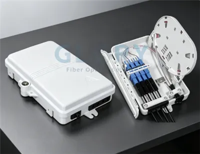
A 2 port fiber termination box is a sealed, wall-mountable or pole-mountable enclosure that provides a protected and organized termination point for fiber optic cables at the final subscriber edge. It integrates four core functions into a single compact housing: fiber splicing, fiber splitting, fiber slack storage, and fiber distribution.
In a standard FTTH architecture, the service provider's last-mile feeder cable runs from the optical distribution frame (ODF) or street-level fiber distribution box (FDB) down to the subscriber premises. The 2-port termination box sits at the building entry - exterior wall, utility pole, or building pedestal - as the first fixed structure the feeder cable encounters. From here, a short drop cable runs indoors to the ONT (Optical Network Terminal) or media converter on the subscriber side.
The NID function: more than a junction box
Most FTTH-grade 2-port fiber termination boxes - including the GL-FTB-4F from Glory Optical - are formally designated Network Interface Devices (NIDs). The NID is the operational boundary between the service provider's infrastructure and the subscriber's premises equipment. Three practical consequences follow:
- It defines the technician access point for fault isolation (provider side vs. subscriber side)
- It protects the provider's feeder infrastructure from subscriber-side physical interference
- It provides the splice and slack storage point that lets a field technician re-splice without re-running cable
Fiber termination box vs. fiber distribution box vs. ODF - the distinction that avoids specification errors
These three terms are frequently used interchangeably and incorrectly. The engineering distinction is hierarchy-based:
A 2-port fiber termination box always sits at the lowest level of this hierarchy - one NID per subscriber or per building face. For MDU deployments with centralized distribution, a larger fiber optic enclosure handles building-level splitting before individual 2-port NIDs serve each residential unit.| Device | Typical port count | Placement in ODN | Primary function |
|---|---|---|---|
| Fiber Termination Box / NID | 1–4 ports | Subscriber premises or building entry | Single-subscriber demarcation, splice, drop cable connection |
| Fiber Distribution Box (FDB) | 8–96 ports | Street-level, corridor, MDU riser | Multi-subscriber distribution, splitter housing |
| ODF (Optical Distribution Frame) | 24–1,000+ ports | Central office / data center | Central cross-connect and routing |
Why two ports - and when to upgrade
The "2 port" specification describes the number of adapter ports on the fiber tray, which directly determines how many live fiber connections can be made inside the enclosure. In a standard FTTH single-subscriber endpoint:
- Port 1 connects the incoming feeder or distribution cable (via spliced pigtail)
- Port 2 connects the drop cable leading to the subscriber's ONT
This is the minimum viable configuration for a single-subscriber residential FTTH drop. The GL-FTB-4F accommodates SC simplex or LC duplex adapters at both ports, with internal space for up to 4 fiber splices on the fusion tray - meaning it also supports a future second fiber pair without enclosure replacement.
When a 2-port box is the right choice
- Single-subscriber FTTH residential endpoints (one duplex service or two simplex)
- Small office or SOHO installations where a compact, low-profile unit is required
- MDU last-meter drops where the building FDB already handles splitting and the 2-port NID is the per-unit interface
- Exterior building entry points where only one drop cable exits the feeder route
When to specify 4 ports or more
Upgrade to a 4-port or larger fiber termination box when the subscriber requires a dedicated fiber per service (data, IPTV, voice on separate fibers), when a 1×2 splitter inside the box must serve two subscriber outputs from one feeder input, or when future expansion to XGS-PON symmetric services requires multiple fiber pairs. Choosing a 2-port box for these scenarios forces a field enclosure swap later - and a swap is rarely just the price of the new box. It is a truck roll, an OTDR trace to confirm the existing path, a re-splice, and subscriber downtime, which is why right-sizing at first install is usually the cheaper path even when the larger enclosure costs more up front.
Technical specifications that actually matter: GL-FTB-4F engineering deep-dive
The GL-FTB-4F 2 port fiber termination box is specified below alongside the engineering reasoning behind each figure, because the datasheet number on its own rarely tells you whether the part fits your route. Six of the headline figures:
IP65 vs IP30 - the line between outdoor viability and premature failure
The GL-FTB-4F carries an IP65 rating under IEC 60529. Breaking down what this means in practice:
- IP6x - Dust-tight: Complete prevention of any dust or particle ingress, regardless of size or sustained exposure.
- IPx5 - Water-jet resistant: Withstands sustained low-pressure water jets (12.5 l/min, 30 kPa) from any direction.
In practice, IP65 means the box can be installed directly on an exterior building wall or utility pole - exposed to rain, dust, and spray - and hold its seal across the product's rated service life under normal outdoor conditions. By contrast, many competing 2-port products carry only an IP30 rating (protection against solid objects >2.5 mm; no moisture protection whatsoever).
The GL-FTB-4F's IP65 rating under IEC 60529 is the minimum specification we would put on any 2-port NID installed on an exterior wall, utility pole, or building pedestal. The failure timelines above are typical of humid and temperate climates; very dry sites degrade more slowly, but specifying an IP30 box for an outdoor position trades a small up-front saving for a likely future truck roll.
| Rating | Dust protection | Moisture protection | Outdoor wall / pole mount? | Typical failure timeline |
|---|---|---|---|---|
| IP30 | Objects >2.5 mm only | None | Not suitable | Condensation within weeks; ingress within 6–18 months |
| IP55 | Dust-protected (limited) | Water jets (limited direction) | Conditional | Depends on mounting orientation and climate |
| IP65 (GL-FTB-4F) | Completely dust-tight | Water jets from all directions | Fully suitable | No ingress under normal outdoor exposure |
A frequent root cause of 2-port termination box failures we see in outdoor deployments is an IP30 indoor-rated box installed on an exterior wall by a subcontractor who did not check the IP rating against the location. The signature is consistent: elevated insertion loss at that NID on the OTDR trace, usually showing up after the first wet season and worsening through later weather cycles as airborne contamination reaches the connector face through the unsealed enclosure. By the time the fault is dispatched, the end-face is contaminated and the pigtail is often degraded - a re-splice, not a wipe-down. Specifying IP65 from the first order avoids the whole sequence.
Temperature range: −40°C to +85°C, and where it actually matters
Many 2-port boxes specify a narrower −20°C to +60°C range. The GL-FTB-4F extends this to −40°C to +85°C, which is the ETSI Class 4.1 ambient envelope for outdoor telecom equipment. The extra headroom matters in three deployment environments in particular:
- Middle East / North Africa: Summer exterior wall surface temperatures routinely exceed +70°C in direct solar exposure. A box rated only to +60°C will see accelerated UV embrittlement and gasket degradation every summer.
- Northern Europe / Canada / Russia: Winter operating temperatures reach −40°C in high-latitude FTTH rollouts.
- Industrial rooftop and tower installations: Roof surfaces in direct sun can exceed +65°C ambient in temperate climates.
IEC 60068 compliance: impact and vibration tested
The GL-FTB-4F is tested to two IEC 60068 environmental reliability standards that are not always listed on competing product pages:
- IEC 60068-2-27 - Shock/impact test (half-sine pulse, 40 g, 11 ms duration). Confirms the enclosure and internal fiber management survive accidental impact during installation, transport, and handling.
- IEC 60068-2-6 - Sinusoidal vibration test. Confirms the unit maintains IP seal integrity and adapter contact on pole-mounted deployments subject to continuous wind-induced vibration (5–150 Hz range).
A utility pole in a coastal or high-wind zone is subject to continuous aeolian vibration - wind-induced oscillation at frequencies typically in the 10–100 Hz range, often sustained for hours. Over months and years, this vibration fatigues plastic enclosure latches, degrades gasket compression, and can work adapter connectors loose from their ports. IEC 60068-2-6 testing validates that the GL-FTB-4F's mechanical design tolerates this load environment without compromising the IP seal or the fiber connection. A box that has not been tested to this standard is an untested assumption on every pole mount in your network.
UL94 V-0 flame rating (optional)
For installations inside residential buildings, riser shafts, or wherever fire safety codes apply, the GL-FTB-4F housing is available with a UL94 V-0 flame retardant rating. Under V-0, the material self-extinguishes in ≤ 10 seconds after flame removal, with no flaming drips. This meets the requirements of NEC Article 770 in the US and equivalent EN/BS standards in European markets for fiber optic equipment installed in occupied buildings.
Insertion loss ≤ 0.2 dB - and why 0.1 dB matters in a real link budget
The GL-FTB-4F specifies insertion loss (IL) ≤ 0.2 dB, inclusive of the installed SC or LC adapter. Most competing 2-port boxes specify IL ≤ 0.3 dB; some specify only ≤ 0.5 dB. In a single-adapter comparison this looks like a rounding error. Across a full GPON path it is not.
In a typical GPON deployment, the maximum allowable path loss from OLT to ONT is 28–32 dB (ITU-T G.984 Class B+ and C+). Each passive component's insertion loss consumes a portion of this budget. With five fiber connection points in the signal path, a 0.1 dB difference per connector adds up to 0.5 dB across the path. How much distance that 0.5 dB represents depends on the operating wavelength: at a typical 1550 nm fiber attenuation of ~0.2 dB/km it is roughly 2.5 km of additional single-mode span, while at the 1310 nm upstream wavelength (~0.35 dB/km) the same 0.5 dB buys closer to 1.4 km. Either way it is budget you either have or you don't - and on a span already near the Class B+ limit, it can be the difference between closing the link and not.
Comparison assumes 5 fiber connection points in a typical FTTH GPON path and expresses reach as the difference from the GL-FTB-4F baseline (1.0 dB total). Each 0.1 dB of IL corresponds to roughly 0.5 km of SMF-28e span assuming ~0.2 dB/km attenuation at 1550 nm; at 1310 nm the equivalent distance is shorter. The figures exclude splitter IL and splice IL, which are constant across options, and ignore margin allocation policy, which varies by operator.
| IL specification | Total consumed (×5 connections) | Effective range impact |
|---|---|---|
| ≤ 0.5 dB (low-quality) | Up to 2.5 dB | ≈ 7.5 km less reach than GL-FTB-4F |
| ≤ 0.3 dB (industry standard) | Up to 1.5 dB | ≈ 2.5 km less reach than GL-FTB-4F |
| ≤ 0.2 dB (GL-FTB-4F) | Up to 1.0 dB | Baseline - maximum link reach preserved |
Return loss: UPC ≥ 50 dB / APC ≥ 60 dB - choosing the right polish for your service mix
Return loss (RL) measures optical power reflected back toward the laser source. High reflected power causes noise in analog video overlays and can damage directly modulated laser sources in some ONT designs.
- UPC (Ultra Physical Contact) polishing achieves RL ≥ 50 dB - suitable for standard GPON data and voice services.
- APC (Angled Physical Contact) polishing achieves RL ≥ 60 dB - required for analog CATV RF overlay, high-power DWDM signals, and any system with a narrowband laser source sensitive to back-reflection.
For hybrid FTTH networks carrying both GPON data and CATV RF overlay (as used in many cable MSO FTTH builds), specify the APC adapter variant at time of order. Mixing UPC and APC connectors in the same fiber path causes high return loss at the interface point - a specification error that cannot be corrected without replacing hardware. Both variants are available for the GL-FTB-4F. The green colour code on APC connectors and adapters distinguishes them from the beige/ivory of UPC in the field.
Adapter selection: SC vs LC, and what each choice commits you to downstream
The GL-FTB-4F ships with either SC simplex or LC duplex adapter slots. The adapter type selected at NID level locks the connector standard for the entire subscriber drop chain - ONT, patch cord, and pigtail must all match.
| Adapter type | Ferrule diameter | Standard for | Specify when |
|---|---|---|---|
| SC simplex | 2.5 mm | GPON ONT interfaces; consumer FTTH globally | Default for residential FTTH / GPON deployments. Pairs with SC pigtails and SC patch cords. |
| LC duplex | 1.25 mm | SFP-based ONTs; enterprise FTTH/FTTB; compact panel density | When the subscriber's ONT or media converter uses SFP transceivers with LC interfaces. Common in commercial FTTB deployments. |
Installing a PLC splitter inside a 2-port fiber termination box
The GL-FTB-4F is designed with a dedicated mounting slot for a micro plug-in type PLC splitter, supporting 1×2 or 1×4 configurations from Glory's PLC splitter range. This converts the NID from a 1-in/1-out subscriber interface into a compact last-drop distribution point.
When to install a splitter inside the NID box
- A single feeder fiber must serve two adjacent subscriber endpoints from one pole-drop NID
- A residential customer requires two separate ONT output paths (e.g., primary router + IP camera network)
- A small MDU where centralized FDB distribution is impractical and two units can share one NID location
Optical budget with a 1×2 PLC splitter in-box
Adding a 1×2 splitter introduces approximately 3.7 dB of insertion loss per output port. For a Class B+ GPON link with a 28 dB budget and 3 dB ODN margin, the full signal path through the GL-FTB-4F in splitter configuration becomes:
| Loss element | Value | Notes |
|---|---|---|
| Box adapter IL | ≤ 0.2 dB | GL-FTB-4F spec |
| 1×2 PLC splitter IL (per output) | ≤ 3.7 dB | Typical micro PLC, ITU-T G.671 |
| Fusion splices (×2, typical) | ≤ 0.10 dB total | 0.05 dB per splice, target |
| Total NID insertion loss | ≤ 4.0 dB | ~14% of Class B+ 28 dB link budget |
For split ratios above 1×4, or for centralized PON distribution to more than four subscribers from one point, the GL-FTB-4F is under-specified by port count alone. Glory's fiber optic enclosures support larger splitter modules and higher port counts. The 2-port NID with built-in micro splitter is the right solution for the final two-drop split at a building face - it is not a substitute for a street-cabinet distribution box handling 8–32 subscribers.
Step-by-step installation - field procedure for the GL-FTB-4F
The following procedure reflects ITU-T L.37 guidance for outdoor ODN equipment installation and typical FTTH contractor standards. The full version is documented in Glory's fiber optic termination box installation guide; the summary below covers the decisions that determine long-term performance.
Before drilling: confirm this is an IP65-appropriate location (any outdoor or semi-exposed site = IP65 minimum). Measure the cable outer diameter - the GL-FTB-4F entry glands accept Ø3–13.5 mm. A gland one size too large will not seal even when fully torqued; a gland-to-cable mismatch is one of the more common causes of IP-rating failure we see in field installs. Select the adapter type (SC UPC, SC APC, or LC duplex) and pre-load the adapter into the tray before mounting if using factory-fit units.
Wall mount: Drill anchor points to match the 208 × 153 mm backplate footprint. Minimum mounting height: 2.5 m above finished grade (ITU-T L.37 ODN outdoor equipment clearance). Orient cable entry ports downward to prevent water pooling at the gland. Torque mounting screws to 3–5 Nm into wall anchors - over-torquing distorts the ABS backplate and misaligns the lid gasket.
Pole mount: Install the anti-vibration rubber liner between the stainless banding clamp and the pole before tightening. Tighten both clamps evenly - uneven torque creates a twisting moment that deforms the gasket seal over time. On high-wind coastal sites, supplement with a lashing wire through the lower clamp to resist axial slippage.
Thread the cable through the compression nut and gland body before screwing the gland into the box port (forgetting this step means pulling the cable back out entirely). Thread the gland in hand-tight, then torque to2.5–3.5 Nmwith a torque wrench. Do not exceed 4 Nm - PG thread stripping is irreversible. For IP68-qualified sites (flood-prone zones), apply self-amalgamating tape over the gland and 50 mm up the cable after closure. Leave1.5 m of fiber slackinside the box for the storage coil and future re-splice reserve.
Strip the cable jacket to 150–200 mm. Do not nick buffer tubes or fiber coatings. Retain the strength member (FRP or steel wire) and attach it to the internal strain relief clamp - this transfers all tensile load away from the fibers. Use a precision fiber cleaver to achieve cleave angles <1°. Splice each fiber to the pigtail end; target splice IL ≤ 0.05 dB. Store splices and protection sleeves in the tray. Maintain bend radius≥ 30 mm throughoutfor G.652D single-mode fiber. If bend radius is constrained, use G.657A2 bend-insensitive fiber, which tolerates bend radii to 7.5 mm.
Connect the pigtail and drop cable connectors to their respective SC or LC adapter ports. Clean each connector end-face with a fiber inspection microscope (100× minimum) before mating - contaminated end-faces are the single largest cause of high insertion loss in field-terminated connections. Apply durable port labels using a consistent scheme (e.g., Service-Provider / Subscriber with cable ID) before closing the lid.
Test with an optical power meter and light source (OPM/OLS pair) or OTDR. Total end-to-end path IL should match the design budget. Any connector showing IL >0.5 dB: clean and retest; if still high, replace the pigtail. Close the lid and visually confirm gasket seating around the full perimeter. For critical sites, perform a low-pressure air test at 0.1–0.2 bar for 5 minutes and confirm no pressure drop before declaring the install complete.
OEM and factory pre-termination: weighing field labor against per-unit cost
Glory Optical's OEM/ODM program supplies factory pre-configured GL-FTB-4F units that reduce on-site installation time and the skill required at each endpoint. The trade is straightforward: you pay more per unit and accept a longer factory lead time, and in return the field crew does less work and needs fewer tools. The table below shows what each configuration includes and roughly what it removes from the field.
| Configuration | What is factory-installed | Typical on-site time saving |
|---|---|---|
| Pre-installed adapters | SC UPC, SC APC, LC UPC, or LC APC adapters mounted and tested | ~5 min |
| Pre-installed micro PLC splitter | 1×2 or 1×4 splitter inserted, labeled, and IL-tested | ~10 min |
| Pre-terminated pigtails | Factory-spliced pigtails to specified length, each tested ≤ 0.1 dB IL | ~20–25 min |
| Full plug-and-play assembly | Adapters + splitter + pigtails pre-installed, box pre-sealed, OTDR-tested at factory | ~30 min vs. field assembly |
| OEM logo / model label | Pad-printed housing with ISP or contractor branding | - |
The arithmetic here is illustrative - substitute your own rates. At a contractor labor rate of $65–85/hr, a 30-minute field splice per endpoint is $32–43 in labor before fusion-splicer amortization (~$15–25/splice), quality risk, and travel between sites. Across a 500-subscriber deployment that is roughly $16,000–$21,500 in splice time alone. Factory pre-termination does not make that cost disappear; it moves most of it off the field crew and into the unit price, where it is fixed and predictable rather than variable and weather-dependent. With a typical pre-termination premium the crossover tends to land somewhere around the 20th–30th endpoint, after which the premium is working in your favor - but the exact breakeven depends on the premium you negotiate and your real field productivity. The other half of the decision is procurement: pre-terminated units are configuration-locked and carry a longer lead time, so they suit planned bulk rollouts more than ad-hoc repairs, where a field-splice kit still earns its place. For OEM pricing and minimum order quantities, contact Glory's quoting team.
Complete ODN ecosystem: Glory components for every layer of the subscriber chain
| Network layer | Glory product |
|---|---|
| Building / street-level distribution | Fiber Optic Enclosure |
| Subscriber NID (this product) | GL-FTB-4F 2 Port Fiber Termination Box |
| In-wall fiber interface at subscriber end | Fiber Optic Wall Outlet |
| Last-mile feeder / drop cable | FTTH Drop Cable |
| Indoor routing cable (G.657A2) | Indoor Fiber Optic Cable |
| Splitter at upstream distribution point | PLC Splitter |
| ONT-side patch cords | Fiber Patch Cord |
| Pigtails for in-box splicing | Fiber Optic Pigtail |
| Field termination without splicer | Fast Connector |
People Also Ask - straight answers
-
Q: What is a 2 port fiber termination box used for?
A: A 2-port fiber termination box is the Network Interface Device (NID) at a single-subscriber FTTH endpoint. It houses and protects the splice point where the service provider's feeder or distribution cable connects to the subscriber's drop cable, provides two fiber adapter ports for connecting patch cords or pigtails, stores fiber slack and fusion splices in a protected tray, and serves as the physical demarcation boundary between provider and subscriber infrastructure. It is the last fixed enclosure before the subscriber's ONT.
Q: What is the difference between a 2-port fiber termination box and a fiber distribution box?
A: A 2-port fiber termination box serves a single subscriber or single building entry point - typically handling 1–4 fiber splices and providing 2 adapter ports for direct fiber connections. It sits at the end of the ODN fiber chain. A fiber distribution box (FDB) serves multiple subscribers from a single upstream location, typically handling 8–96 fibers with multiple output ports and internal splitter capacity. The distribution box is upstream in the ODN hierarchy; the 2-port NID is downstream of it.
Q: What does IP65 mean for an outdoor fiber termination box?
A: IP65, defined by IEC 60529, means the enclosure is completely dust-tight (the "6" digit) and resistant to water jets from all directions (the "5" digit - sustained low-pressure jets at 12.5 l/min / 30 kPa). An IP65-rated outdoor fiber termination box can be installed on exterior walls or utility poles and remain fully sealed during rain, dust storms, and cleaning sprays. IP30-rated "indoor" boxes installed outdoors commonly develop condensation within weeks and can show visible moisture ingress within roughly 6–18 months in humid and temperate climates.
Q: Can a PLC splitter be installed inside a 2-port fiber termination box?
A: Yes, in the GL-FTB-4F specifically. The enclosure has a dedicated mounting slot for a micro plug-in 1×2 or 1×4 PLC splitter. Installing a 1×2 splitter adds approximately 3.7 dB of insertion loss per output port but allows one incoming feeder fiber to serve two subscriber drop cables from a single NID. The total NID path loss in this configuration is approximately ≤ 4.0 dB, which is within the GPON Class B+ link budget for spans up to approximately 12–15 km.
Q: How many fibers can a 2-port fiber termination box hold?
A: The GL-FTB-4F has 2 adapter ports for active fiber connections and a fusion splice tray that stores up to 4 fiber splices with protection sleeves. This supports a 2-fiber duplex feeder cable (transmit + receive) with active adapter connections, while retaining spare splice capacity for a future second fiber pair - without enclosure replacement. For 4 or more active adapter ports, see the Glory fiber termination box range.
Q: What is the minimum bend radius inside a fiber termination box?
A: The minimum bend radius for standard single-mode fiber (G.652D, SMF-28 equivalent) is 30 mm at the operating condition. The GL-FTB-4F's internal tray and storage ring maintain ≥ 30 mm throughout the fiber routing path by design. If tighter bends are unavoidable due to installation geometry, specify G.657A2 bend-insensitive fiber, which tolerates bend radii to 7.5 mm with negligible macrobending loss per IEC 60793-2-50.
Q: How do I install a 2-port fiber termination box outdoors?
A: Six steps: (1) Pre-installation check - verify IP65 rating for the location, measure cable OD, select gland size, pre-load adapters. (2) Mount the box at ≥ 2.5 m height with cable entry ports facing downward. (3) Seal the cable entry - match gland to cable OD, torque to 2.5–3.5 Nm. (4) Splice fibers to pigtails with target splice IL ≤ 0.05 dB, maintain ≥ 30 mm bend radius throughout. (5) Connect and test - clean end-faces, connect adapters, verify with OTDR or OPM. (6) Close and seal - verify gasket seating. The full procedure is in the Glory installation guide.
Q: What adapter types does a 2-port fiber termination box support?
A: The GL-FTB-4F supports SC simplex (standard for FTTH/GPON, 2.5 mm ferrule) and LC duplex (for SFP-based ONTs, 1.25 mm ferrule), in both UPC polish (return loss ≥ 50 dB, standard GPON data/voice) and APC polish (return loss ≥ 60 dB, analog CATV overlay and DWDM). The adapter type must be specified at order time; factory pre-installation is available for all four combinations. Never mix UPC and APC connectors in the same fiber path - the mating interface will produce high back-reflection and elevated insertion loss.
Q: What certifications should an outdoor fiber termination box carry?
A: For outdoor deployment the minimum certifications to verify are: IP65 per IEC 60529 (environmental sealing); IEC 60068-2-6 (vibration - mandatory for pole-mount sites); IEC 60068-2-27 (shock/impact); and UL94 V-0 flame rating for any indoor or building-interior installation. For global market access, CE marking confirms compliance with EU product safety directives and RoHS confirms restricted substance compliance. The GL-FTB-4F carries all of the above. Ask any supplier for the test reports - a sticker without a report is a claim, not a certification.
Q: Is a 2-port fiber termination box the same as a fiber junction box?
A: Not precisely, though the terms overlap. A fiber termination box (or NID) specifically provides both splice storage and adapter connection ports for active fiber termination at a subscriber endpoint. A fiber junction box often refers to a sealed enclosure for mid-span or branch splice points that may not include adapter connection ports. In common usage, both terms describe a sealed enclosure for fiber connections - but when specifying for FTTH subscriber demarcation, use "fiber termination box" or "NID" to make the function clear.
The engineer's verdict
Specifying a 2-port fiber termination box is less a box decision than an infrastructure decision, because whatever you choose repeats at every endpoint you deploy. A box that fails its IP rating in the first wet season costs you more than the replacement enclosure: a dispatch visit, an OTDR trace, a re-splice, and the subscriber downtime between failure and truck roll. Getting the specification right at order time is almost always cheaper than the maintenance visit it prevents.
Glory Optical has manufactured passive optical network components to ISO 9001:2015, CE, and RoHS standards since 2008, and ships to operators in 50+ countries. If you want to check the GL-FTB-4F against your route - link budget, splitter ratio, cable OD, temperature zone, pre-termination configuration - see our full fiber termination box range, review the complete installation handbook, or contact our engineering team with your cable counts, adapter type, and deployment environment. Send the route details and we will tell you plainly whether it fits - and where it doesn't.